
Image processing system

a technology of image processing and image, applied in the field of image processing system, can solve the problems of difficult to simplify the image processing system, the influence of external light such as sunlight cannot be prevented, and it is difficult to decide whether the reflected light comes from outside the window or inside the vehicl

Active Publication Date: 2006-11-02
HITACHI ASTEMO LTD
View PDF19 Cites 13 Cited by
  • Summary
  • Abstract
  • Description
  • Claims
  • Application Information

AI Technical Summary

Benefits of technology

The system provides a simplified and reliable method for detecting foreign matter on windows, capable of capturing images under multiple conditions without mechanical parts, improving visibility and durability in harsh ambient conditions.

Problems solved by technology

This poses various problems.
One problem is that it is difficult to simplify the image processing system.
Another problem is that the influence of external light such as sunlight cannot be prevented.
Furthermore, for the technique that uses one light source for detection of reflected light, it is difficult to decide whether reflected light comes from outside the window or inside it and it is also hard to detect a white line ahead of the user's own vehicle or a vehicle in front at the same time because the lens is focused on the window.
With the above conventional techniques, it is impossible to capture images at a time under a plurality of conditions or to capture images successively under a plurality of conditions.
However, because the conventional techniques involve mechanical movement, it is difficult to deal with high image processing speeds.
In this sense, products with mechanically movable parts are not desirable from the viewpoint of reliability.

Method used


Image

  • Image processing system
  • Image processing system
  • Image processing system

Examples


Embodiment Construction

[0039] Next, preferred embodiments of the present invention will be described referring to the accompanying drawings.

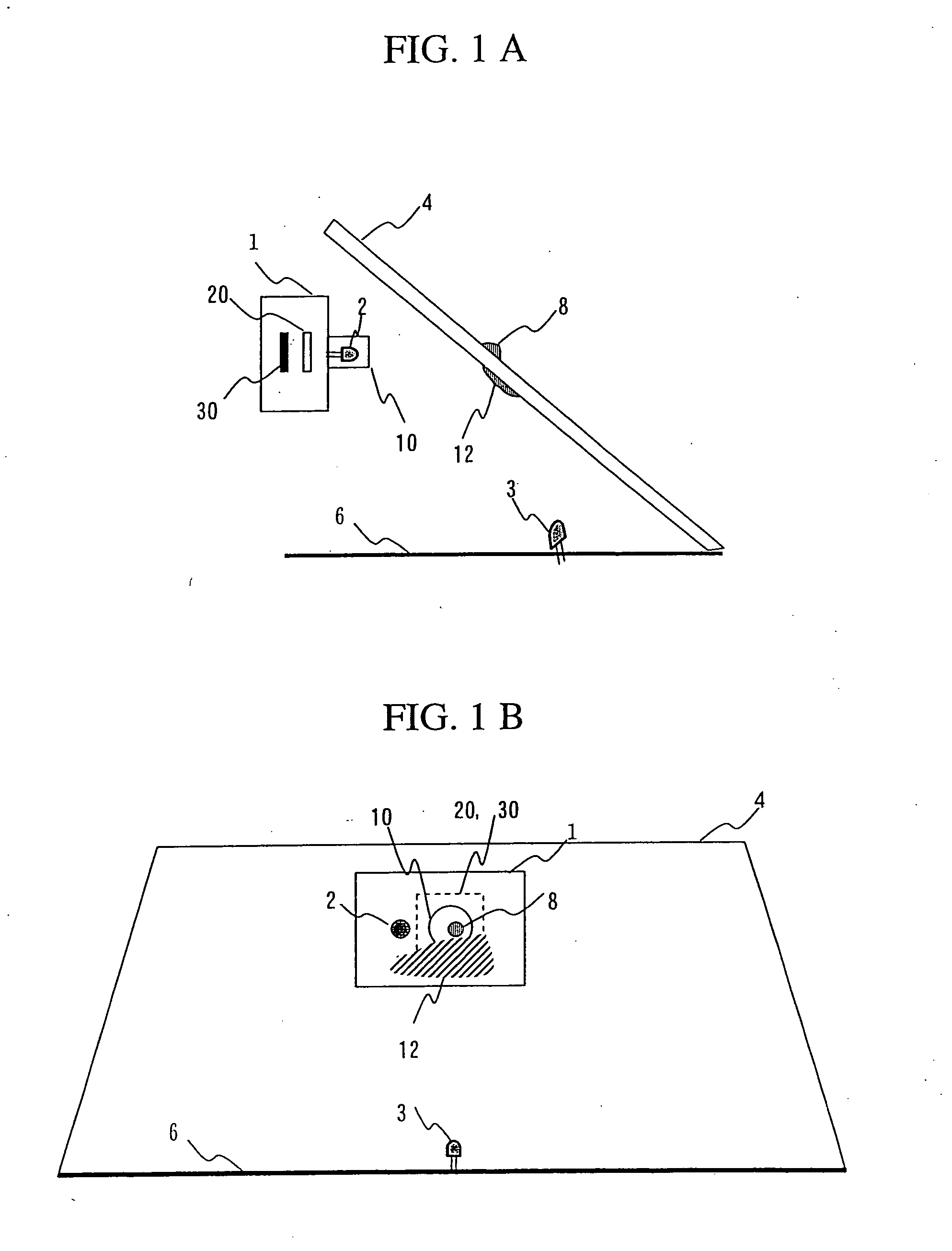
[0040]FIG. 1A is a sectional side view of an image processing system according to an embodiment of the present invention and FIG. 1B is a front view of it as seen through windshield from outside a vehicle.

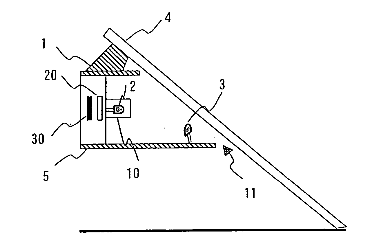
[0041] This image processing system consists of an image processor 1, a first lamp 2 and a second lamp 3. The time to turn on the first lamp 2 and second lamp 3 is controlled by the image processor 1. The image processor is installed inside the vehicle facing windshield 4. The first lamp 2, located alongside the image processor 1, emits light toward the windshield 4. The second lamp 3 emits light toward the windshield 4 upwards or from below.

[0042] A drive circuit in the image processor 1 turns on the first lamp 2 to emit light toward the windshield 4. The light emitted from the first lamp 2 passes through the windshield 4 when the glass is clean. The light reflec...


PUM

PropertyMeasurementUnit
transmittanceaaaaaaaaaa
wavelengthaaaaaaaaaa
infrared wavelength rangeaaaaaaaaaa

Abstract

An image processing system includes a lamp which emits light to a glass, an imaging device which captures light which is emitted from the lamp and reflected by the glass, and an optical filter, located between the glass and the imaging device, which transmits rays with a specific wavelength of the reflected light. A lens is provided in front of the imaging device, and a focus of the lens is adjusted to a point beyond the glass, and an image processor is provided which processes an image captured by the imaging device and detects moisture on the glass.

Description

CROSS REFERENCE TO RELATED APPLICATION [0001] This application is a continuation application of U.S. application Ser. No. 10 / 916,444, filed Aug. 12, 2004, the contents of which are incorporated herein by reference.BACKGROUND OF THE INVENTION [0002] 1. Field of the Invention [0003] The present invention relates to an image processing system which is suitable for detection of foreign matter on surfaces of various types of window. [0004] 2. Description of Related Art [0005] Droplets such as raindrops, fog and dust on surfaces of window glass used in vehicles, ships and aircraft or in ordinary buildings deteriorate the visibility of the window. A known solution to this problem is an image processing system which detects such foreign matter and removes it by various means. [0006] Patent Literature 1 (JP-B No.89099 / 1995) discloses a technique that window is illuminated by two light sources and reflected light from the window is detected by an imaging device and raindrops on the outer surf...

Claims


Application Information

Patent Timeline
Patent Type & Authority Applications(United States)
IPC IPC(8): G02B6/42H01L27/00G01N21/94B60R1/00B60S1/08G01N21/17G01W1/11G01W1/14
CPCB60S1/0818B60S1/0822B60S1/0896B60S1/0844B60S1/0833G06V20/56
Inventor TAKENAGA, HIROSHIOTSUKA, YUJIMURAMATSU, SHOJIMONJI, TATSUHIKOOHSUMI, KENFURUSAWA, ISAOFUKUHARA, MASAAKIKASUYA, HIROYUKI
Owner HITACHI ASTEMO LTD
Learn More