
Lighting device with integration sheet

a technology of light source and integrated sheet, which is applied in the direction of lighting device details lighting and heating apparatus, etc., can solve the problems of poor energy efficiency and glare control of devices adopting semi-transparent plastic screens as shielding screens, and the limited types and structures of light sources, so as to enhance the luminous efficacy of lighting devices and improve the uniformity of lighting devices. illuminance

Active Publication Date: 2006-10-19
ACER INC
View PDF7 Cites 24 Cited by
  • Summary
  • Abstract
  • Description
  • Claims
  • Application Information

AI Technical Summary

Benefits of technology

[0006] It is the primary object of the present invention to provide a lighting device with integration sheet capable of collimating the scattered light beams to incident on an intended illuminating area and diffusing the light beams emitting from the center of the light source to incident on the same by the operations of the partitions formed on the sheet, so that not only the luminous efficacy of the lighting device is enhanced, but also the uniformity of the illuminance of the lighting device is improved.
[0007] Another object of the invention is to provide a lighting device comprising a sheet with a plurality of microstructures formed thereon, capable of enabling the lighting device to have uniformly distributed luminance by designing various microstructures with different base widths.

Problems solved by technology

However, since the semi-transparent plastic screen is inferior in that it is capable of not only absorbing light, but also diffusing light, the lighting device adopting semi-transparent plastic screen as shielding screen will have poor energy efficiency and glare control.
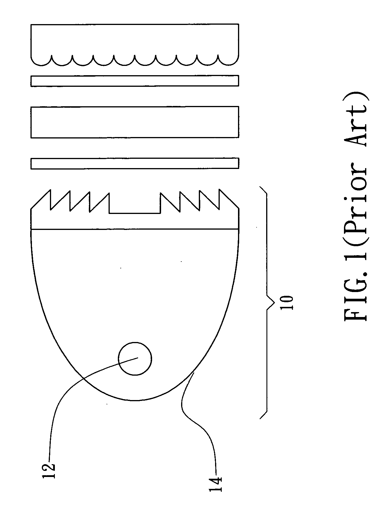
However, since the goal of the light box 10 is to discharge parallel rays, the types and structures of the light source are thus limited.
Although the direction and distribution of the emitted light is controllable by the catadioptric lens, it is bulky and complicated that is not cost effective.

Method used


Image

  • Lighting device with integration sheet
  • Lighting device with integration sheet
  • Lighting device with integration sheet

Examples


second embodiment

[0032] Please refer to FIG. 3, which is a three dimensional diagram illustrating a sheet according to the invention. In this preferred embodiment shown in FIG. 3, the sheet 3 is formed by laminating a first plate 31 and a second plate 32, whereas a microstructure array 311 is formed on a surface of the first plate 31 and another microstructure array 321 is formed on a surface of the second plate 32 opposite to the microstructure array 311. Moreover, the sheet 3 is designed to correspond to the distribution of light emitted from the lighting device, such that the contour of the sheet 3 is a shape selected form the group consisting of a hexagon, a triangle, a pentagon, a quadrangle, and the combination thereof.

[0033] Please refer to FIG. 4A, which is a schematic diagram illustrating the microstructures formed on a sheet according to a third embodiment of the invention. The base widths of the microstructures of any array out of the plural arrays formed on the sheet 7 can be equal to or...

fifth embodiment

[0034] Please refer to FIG. 5A, which is a schematic top view of a screen according to the invention. The sheet 6 shown in FIG. 5A comprises a plurality of light diffusion zones 61, whereas any one of the plural light diffusion zones 61 can be a Fresnel lens as shown in FIG. 5B.

[0035] For enabling a lighting device to have good heat dissipating ability, apertures are formed on the sheet for conducting heat generated by the light source out of the lighting device. Accordingly, the sheet with heat conducting structure is able to reduce the hazard of overheating and thus increase the usage time of the lighting device. Please refer to FIG. 6A, which is a schematic diagram depicting a heat conducing structure according to a preferred embodiment of the invention. In the preferred embodiment shown in FIG. 6A, a plurality of apertures 41 are formed on the sheet 4 for conducting heat. Please refer to FIG. 6B, which is a schematic diagram depicting a heat conducing structure according to anot...


PUM


Abstract

A light device with integration sheet is disclosed, which comprises: a light source; and at least a sheet, each being disposed at the light emitting end of the light source and comprising a plurality of light diffusion zones; wherein each light diffusion zone has a plural arrays of microstructures arranged on the surface thereof, and each array of microstructures is capable of changing the diopter of the corresponding light diffusion zone. By controlling the distribution of the plural arrays of microstructures, the Gaussian distribution of the light source can be improved while collimating the scattered light beams to the intended illuminating area of the lighting device and diffusing the light beams emitting from the center of the light source to the same so that not only the luminous efficacy of the lighting device is enhanced, but also the uniformity of the illuminance of the lighting device is improved.

Description

FIELD OF THE INVENTION [0001] The present invention relates to a lighting device, and more particularly, to a lighting device with integration sheet capable of using a sheet having a plural arrays of microstructures arranged thereon, the sheet being designed basing on an energy distribution of a light source calculated by a means of integration, to improve the uniformity of the light beams discharged form the lighting device while enhancing the luminance of the same. BACKGROUND OF THE INVENTION [0002] It is known that the illumination quality and the property of the light of a lighting device are related to the way that light beams generated by the lighting device are being transmitted. Lighting analysis of a lighting device incorporates lighting levels and lighting quality considerations such as glare, uniformity of illuminance, and color rendition into a lighting survey. Generally, a lighting device uses reflecting screens and shielding screens to control the directions of the lig...

Claims


Application Information

Patent Timeline
IPC IPC(8): F21V5/02
CPCF21V5/02F21V5/002
Inventor LIN, JIAN-SHIANHSU, HSIU-CHENCHEN, MING-FONGLIN, BEN-SHENG
Owner ACER INC
Learn More