Method and system for automatic target finding
- Summary
- Abstract
- Description
- Claims
- Application Information
AI Technical Summary
Benefits of technology
Problems solved by technology
Method used
Image

Examples
Embodiment Construction
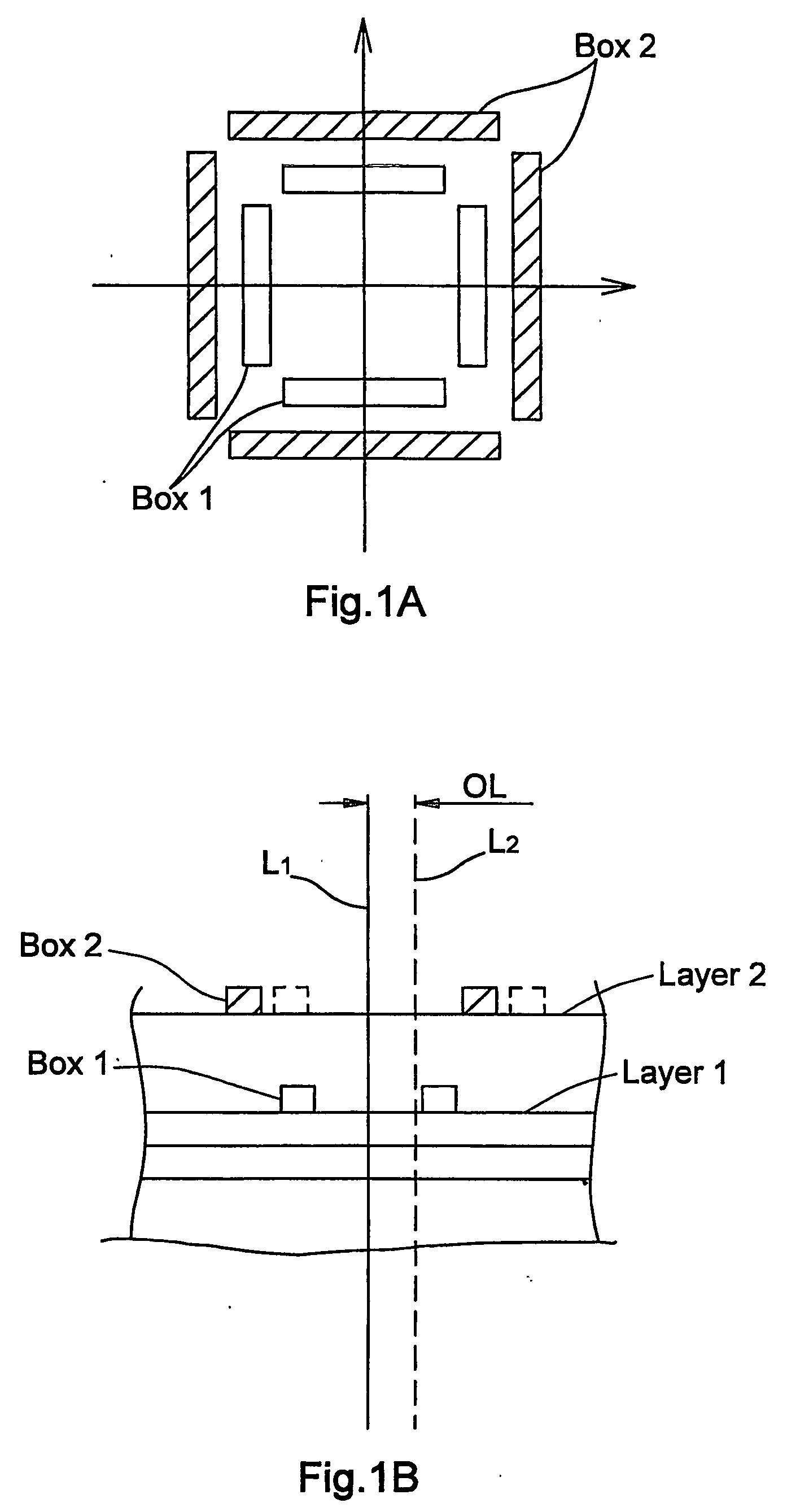
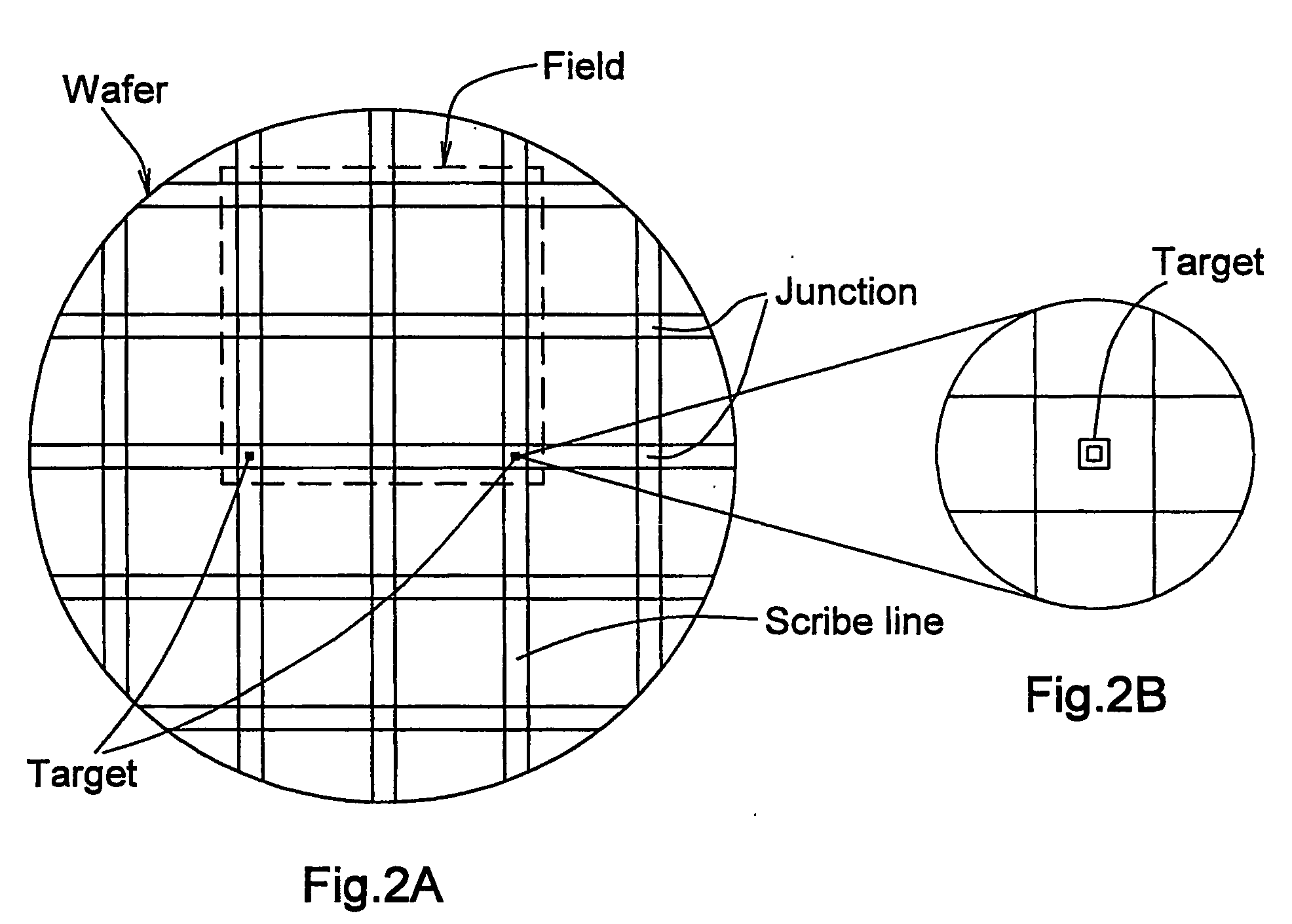
[0035]FIGS. 1A and 1B illustrate a bar-in-bar target structure, showing a perfect alignment (registration) between two patterned target-containing layers (when the centers of the bars are located in the same place) and a misregistration between the layers (when the image of one target is shifted relative to that of the other). FIGS. 2A and 2B illustrate a die map in the form of the distribution of dies over a wafer. A box-on-box target is typically located in a junction region of the die map.
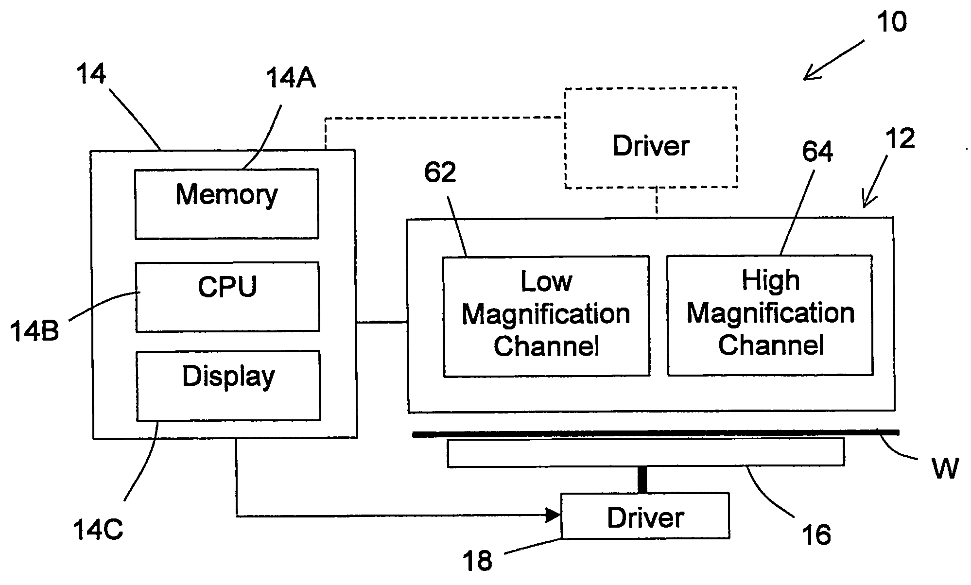
[0036] Referring to FIG. 3, there is schematically illustrated a measurement system 10 according to the invention for overlay measurements on a wafer W. The system 10 comprises such main constructional parts as a measuring unit 12 and a control unit 14.
[0037] The measuring unit 12 includes an optical arrangement defining two light propagation channels of different image magnifications—a relatively low magnification channel 62 (e.g. 0.3-1.0×.) and a relatively high magnification channel 64 (e.g...
PUM
 Abstract
Description
Claims
Application Information
 - R&D
- Intellectual Property
- Life Sciences
- Materials
- Tech Scout
- Unparalleled Data Quality
- Higher Quality Content
- 60% Fewer Hallucinations
Browse by: Latest US Patents, China's latest patents, Technical Efficacy Thesaurus, Application Domain, Technology Topic, Popular Technical Reports.
© 2025 PatSnap. All rights reserved.Legal|Privacy policy|Modern Slavery Act Transparency Statement|Sitemap|About US| Contact US: help@patsnap.com