
Actuator, liquid drop discharge head, ink cartridge, inkjet recording device, micro pump, optical modulation device, and substrate

a liquid drop discharge and actuator technology, applied in the direction of piezoelectric/electrostrictive/magnetostrictive devices, instruments, printing, etc., can solve the problems of reducing the reproducibility of image quality, affecting the reliability, and affecting the accuracy of printing. high precision and reliability

Inactive Publication Date: 2006-10-19
RICOH KK
View PDF13 Cites 10 Cited by
  • Summary
  • Abstract
  • Description
  • Claims
  • Application Information

AI Technical Summary

Benefits of technology

[0013] Another and more specific object of the present invention is to provide an actuator having high precision and reliability, and a liquid drop discharge head, ink cartridge, inkjet recording device, micro pump, and optical modulation device which have the actuator, whereby a sacrificial layer elimination hole is sealed under atmospheric conditions without using a vacuum device so that a deposition film is effectively prevented from invading in a first space.

Problems solved by technology

Especially, in a case of the ink jet heads, the larger the dispersion of the capacity of the actuators is, the more printing precision and reproducibility of image quality are reduced.
However, in this deposition method, a deposition component may invade (seep into) the space.
If the deposition component invades the space, a vibration property of the vibration plate is changed so that a bad influence is given to the reliability.
In addition, since the sacrificial layer elimination hole is also used for ensuring the strength of a partition, it is not possible to make the hole small and therefore the hole is not appropriate for being made at a high density.
However, in this method, since a process is performed in the vacuum state, the pressure in the space may be negative when atmospheric exposure occurs.
Hence, it is not possible to obtain a desirable amount of bending deformation of the vibration plate and deformation dispersion may be generated due to the dispersion of the bending.
A structure or process opening to the air is required to solve the above-mentioned problems and this may cause increase of cost or decrease of yield rate.
Thus, in the related art, it is difficult to obtain the actuator having high precision and using an electrostatic force with high reliability at low cost.

Method used


Image

  • Actuator, liquid drop discharge head, ink cartridge, inkjet recording device, micro pump, optical modulation device, and substrate
  • Actuator, liquid drop discharge head, ink cartridge, inkjet recording device, micro pump, optical modulation device, and substrate
  • Actuator, liquid drop discharge head, ink cartridge, inkjet recording device, micro pump, optical modulation device, and substrate

Examples


first example

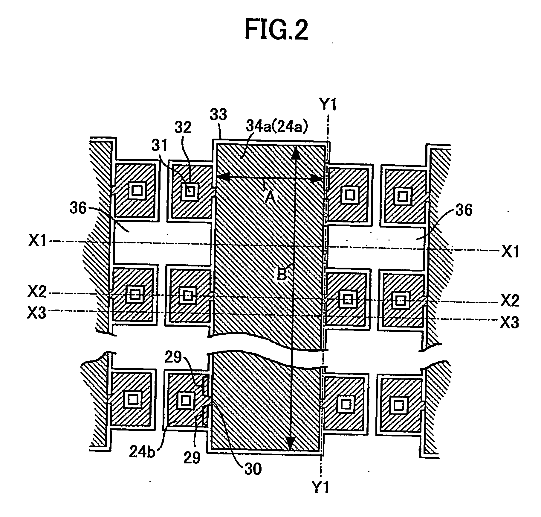
[0127] A main part structure of the actuator is discussed with reference to FIG. 2 through FIG. 11. FIG. 2 through FIG. 4 show an actuator part of the liquid drop discharge head 200 of the first example. FIG. 2 is a plan view of the actuator part. FIG. 3 is a Y1-Y1 cross-sectional view of the substrate shown in FIG. 2. FIG. 4-(a) is an X1-X1 cross-sectional view of the substrate shown in FIG. 2. FIG. 4-(b) is an X2-X2 cross-sectional view of the substrate shown in FIG. 2. FIG. 4-(c) is an X3-X3 cross-sectional view of the substrate shown in FIG. 2.

[0128]FIG. 5-(a) through FIG. 10-(a) are X2-X2 cross-sectional views of the actuator shown in FIG. 2. FIG. 5-(b) through FIG. 10-(b) are Y1-Y1 cross-sectional views of the actuator shown in FIG. 2. These drawings are described by following an order of the manufacturing steps of the actuator.

[0129]FIG. 11-(a) is a plan view of the vicinity of the sacrificial layer removing hole. FIG. 11-(b) is a Y1-Y1 cross-sectional view of the vicinity ...

second example

(Structure of Actuator)

[0164] The second example is discussed with reference to FIG. 17 through FIG. 27.

[0165]FIG. 17-(a) is a plan view of the actuator of the liquid drop discharge head 200 and FIG. 17-(b) is a Y1-Y1 cross-sectional view of FIG. 17-(a). FIG. 18 is an X1-X1 cross-sectional view of the substrate shown in FIG. 17. FIG. 19 is an X2-X2 cross-sectional view of the substrate shown in FIG. 17. FIG. 20 is an X3-X3 cross-sectional view of the substrate shown in FIG. 17. FIG. 21 through FIG. 27 are views showing a manufacturing process of the substrate. For the convenience of explanation, only a single actuator is shown in FIG. 21 through FIG. 27.

[0166] As shown in FIG. 17 through FIG. 20, the vibration plate area 74a is separated from the partition part 66 by the separation groove 63 filled with the material. The vibration plate area 74a has a film structure where the insulation film 65, the upper electrode 66, the film bending prevention film 67 and the resin film 68 ar...

third example

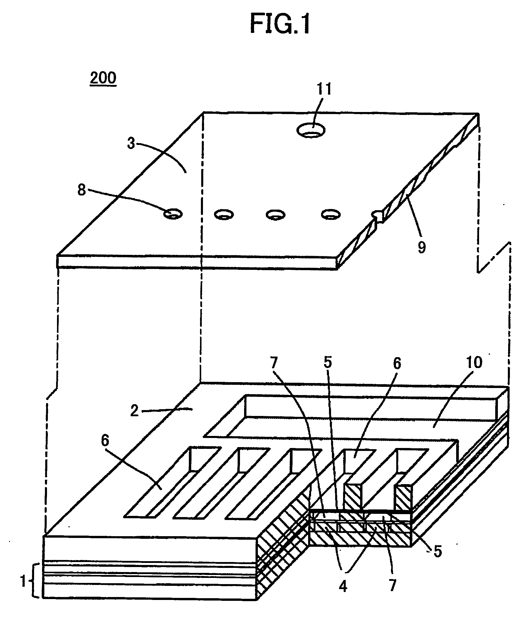
[0192] The third example is discussed with reference to FIG. 31 and FIG. 32. FIG. 31 shows a part of the liquid drop discharge head 200 wherein a connection tube (substrate) 800 having the first space 24a or 74a of the actuators 90, 91 and 92 formed by the manufacturing method of the actuator in the first and second examples and the first spaces are connected. A buffer room 820 shown in FIG. 32 or a buffer room 821 shown in FIG. 33 is connected to an extended part from the connection tube 800 shown in FIG. 31.

[0193]FIG. 32-(a) is a plan view of the buffer room 820 and FIG. 32-(b) is a cross-sectional view of a barrier part in the buffer room. FIG. 33-(a) is a plan view of the buffer room 821 and FIG. 33-(b) is a cross-sectional view of a barrier part in the buffer room.

[0194] It is normal that an actuator part (space part) of the liquid drop discharge head including the actuators 90 through 92 shown in FIG. 31 is insulated from the outside in order to prevent degradation of the pr...


PUM


Abstract

An actuator includes a vibration plate area displaced by an electrostatic force, and electrodes facing each other via a first space in the vibration plate area The first space is formed by a sacrificial layer process using a sacrificial layer removing hole. A barrier as a fluid resistance is formed between the first space and a second space situated in the vicinity of the sacrificial layer removing hole.

Description

TECHNICAL FIELD [0001] The present invention relates to actuators, liquid drop discharge heads, ink cartridges, inkjet recording devices, micro pumps, optical modulation devices, and substrates, and more specifically, to an electrostatic actuator, liquid drop discharge head, ink cartridge, inkjet recording device, micro pump, optical modulation device, and substrate which use the actuator. BACKGROUND ART [0002] In an ink jet recording apparatus used as a picture recording apparatus or picture forming apparatus such as a printer, facsimile, or copier, a liquid drop jet head is used as an ink jet head configured to discharge (jet out) ink. [0003] The ink jet head includes a nozzle, a discharging room, a common room, and pressure generating means. An ink drop is discharged by the nozzle. The nozzle is connected to the discharging room. The discharging room is called a pressurized liquid room, pressure room, ink channel, or the like. Discharging fluid (ink) supplied to the discharging r...

Claims


Application Information

Patent Timeline
IPC IPC(8): B41J2/045B41J2/055B41J2/14B41J2/16B81B3/00G02B26/08
CPCB41J2/14314B41J2/16B41J2/1628B41J2/1629G02B26/0841B41J2/1639B41J2/1642B41J2/1645B41J2/1631
Inventor KURODA, TAKAHIKOABE, SHUYA
Owner RICOH KK
Learn More