Eureka AIR delivers breakthrough ideas for toughest innovation challenges, trusted by R&D personnel around the world.

System for the relative navigation of aircraft and spacecraft using a phased array antenna

a technology of phased array antennas and radio navigation systems, applied in the field of navigational systems, can solve the problems of disadvantageous rotation of radio beacons, simple and more compact electronic systems, and limited size and weigh

Inactive Publication Date: 2006-10-19
MALLICK BRIAN
View PDF9 Cites 12 Cited by
  • Summary
  • Abstract
  • Description
  • Claims
  • Application Information

AI Technical Summary

Benefits of technology

"The present invention provides a radio navigation system and a method of operating it using unmodulated radio signals of a single frequency that are transmitted as a series of radio pulses. The system uses a radio phased array antenna panel that is common to military and airport radar systems. The system measures the power of the received radio signals and stores it in memory. After a series of signals are received and at least two signal strength measurements are stored, the system calculates the ratio or ratios of each signal strength per time interval. Bearing is then determined by comparing the calculated signal power ratios with a library of angles that correspond to specific signal power ratios. Range is determined by either measuring the signal round-trip travel time after a query signal is sent from the receiver location, or by comparing the received power ratios with what the power ratio would be from the transmitting location using the inverse square law equation that defines power dissipation with distance. The invention reduces the amount of electronic equipment required and allows for more efficient and accurate navigation."

Problems solved by technology

However, in many aircraft and spacecraft there are size and weight limitations that require that a simple and more compact electronic system be used.
Rotating the radio beacon is disadvantageous because the navigational signal is transmitted to only a small volume of space at any one time.
Modulating the radio beacon is disadvantageous because the time consumed in modulating and demodulating the signal limits the repeat transmission rate of the navigational signal.
This is disadvantageous because it requires more equipment than utilizing just a single frequency.

Method used


Image

  • System for the relative navigation of aircraft and spacecraft using a phased array antenna
  • System for the relative navigation of aircraft and spacecraft using a phased array antenna
  • System for the relative navigation of aircraft and spacecraft using a phased array antenna

Examples


Embodiment Construction

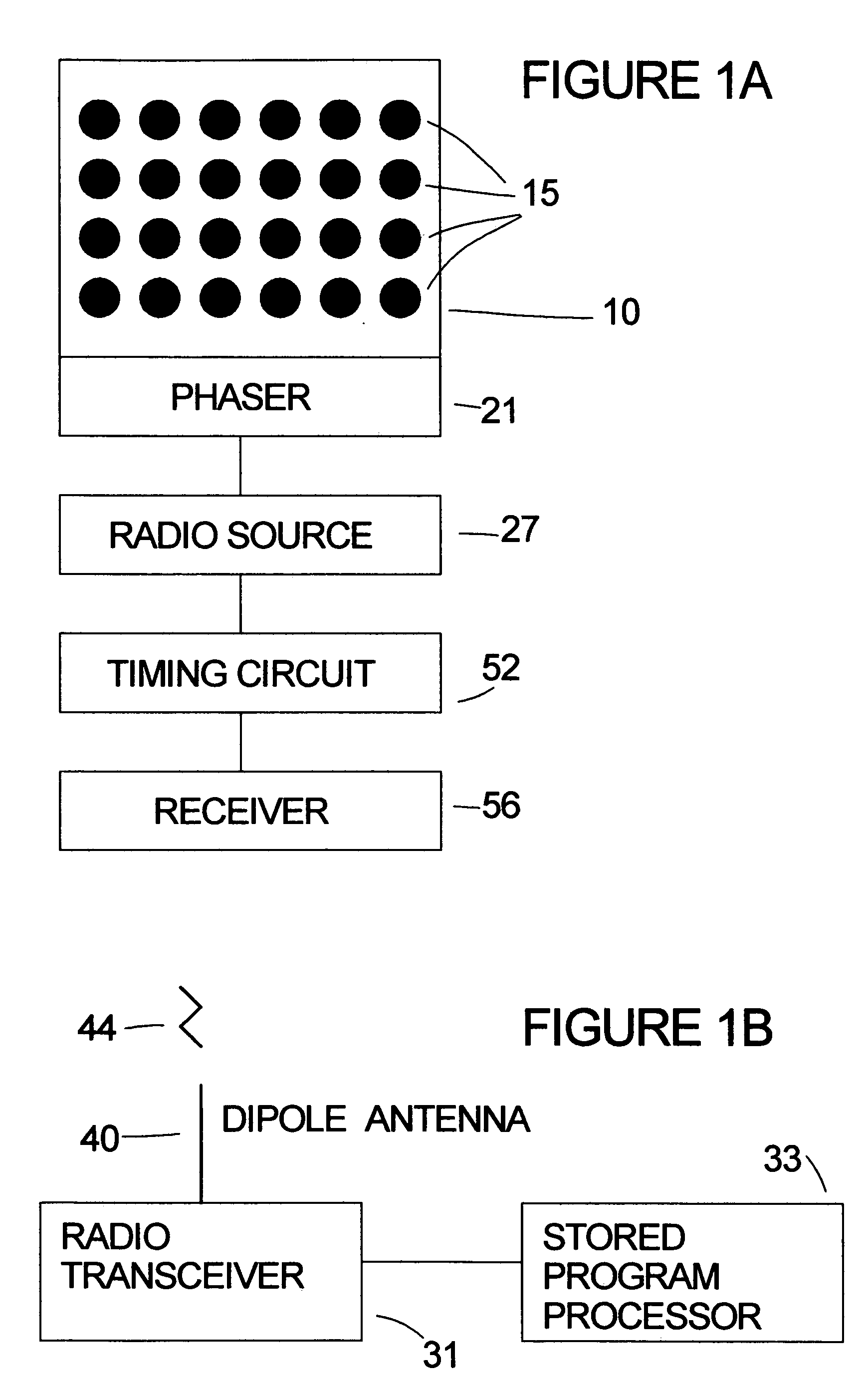
[0016] Referring to the FIG. 1A, a phased array panel 10 at a transmitting station has a plurality of circular microstrip antennas 15 on it. Each microstrip antenna 15 is conductively connected to the phaser circuitry 21 that controls the time that the radio signal from the radio source 27 is received by each antenna element 15 for transmission. This time difference affects the phase for each antenna signal and hence the directionality of the combined signal from all antennas. Attached to the radio signal source 27 is a computer-controlled timing circuit 52 that energizes the array. Attached to the timing circuit 52 is a receiver 56 that receives a query pulse.

[0017] In one embodiment, phased array antenna panel 10 comprises 24 circular microstrip antennas 15 in a four row by six column array. A radio navigation system in accordance with the present invention may work with as few as four microstrip antenna elements; however, the more microstrip antenna elements there are in the pha...


PUM


Abstract

A system for the relative navigation of aircraft and spacecraft is disclosed which uses a series of short duration, unmodulated radio pulses transmitted from a phased array antenna. The aircraft or spacecraft whose position is to be determined from another is called as the local station, whereas the other craft with the phased array antenna system is called as the transmitting station. The local station transmits a radio query pulse to the transmitting station. In response to the radio query pulse, the transmitting station transmits a series of unmodulated radio pulses, where each radio pulse is transmitted with a three dimensional radiation pattern that is different than the three dimensional radiation patterns of the other radio pulses transmitted by the transmitting station. A receiver attached to the local station aircraft or spacecraft receives each radio pulse, generates a signal that describes the radio signal strength of the received signal and sends that signal strength number to a stored program processor which stores that signal strength number into memory. After a series of radio signals are received at the local station and at least two radio signal strength measurements are stored in memory, the stored program processor calculates the power ratio or ratios of each received radio signal strength from each radio pulse transmitted by the transmitting location. Bearing is then determined by comparing the calculated radio signal power ratios with a library of angles that correspond to specific power ratios for all radio radiation patterns transmitted. The local station also records the time elapsed from when the first radio pulse is received from the transmitting station after the radio query pulse is sent. Range is determined by dividing that elapsed time by two and multiplying that time with the speed of light.

Description

BACKGROUND OF THE INVENTION [0001] 1. Field of the Invention [0002] This invention relates to a navigational system for determining the bearing and distance of one aircraft or spacecraft with respect to another, the two objects being above ground in the Earth's atmosphere or in outer space. It more particularly relates to a radio navigation system using a set of pulses of unmodulated radio beacons of a specific frequency transmitted from a phased array antenna. [0003] 2. Description of the Prior Art [0004] U.S. Pat. No. 4,823,137 to Mallick describes a navigational system using an array of fixed, directional antennas for broadcasting unmodulated radio signals at several different frequencies. Each antenna is conductively coupled to a transmitter that provides the unmodulated radio signal to the antenna, and each antenna transmits a radio signal of a different frequency from the frequencies of transmission of other antennas in the array. Since each antenna is pointing in a different ...

Claims


Application Information

Patent Timeline
Patent Type & Authority Applications(United States)
IPC IPC(8): G01S1/08
CPCG01S1/12G01S13/785G01S11/06
Inventor MALLICK, BRIAN
Owner MALLICK BRIAN
Why Eureka
Eureka Blog
Learn More