Valve for controlling a fluid

a valve and fluid technology, applied in the direction of valve operating means/release devices, mechanical equipment, machines/engines, etc., can solve the problems of premature failure of the valve's functionality and material wear, and achieve the effect of reducing noise generation

Inactive Publication Date: 2006-10-19
ROBERT BOSCH GMBH
View PDF6 Cites 19 Cited by
  • Summary
  • Abstract
  • Description
  • Claims
  • Application Information

AI Technical Summary

Benefits of technology

[0019] To prevent the compression pulse from being transferred to the valve closure member, it is useful if a damping tube that is preferably located after the throttling element has a diameter that corresponds to at least three times the throttling element diameter.
[0020] In order to keep the Mach number of the gas flow at the exit of the damping tube well below 1, and to bring about a substantial reduction in noise generation, it is useful if the damping tube has a length that corresponds to at least ten times the throttling element diameter.

Problems solved by technology

In known gas valves of the kind described, the problem exists that when an oil-free gas is used, material wear occurs in the region of the valve armature and the valve seat because of the absence of lubrication, and that the valve armature can tilt and thus become jammed on the valve body, which in turn results in premature failure of the valve's functionality.

Method used


Image

  • Valve for controlling a fluid
  • Valve for controlling a fluid
  • Valve for controlling a fluid

Examples


Embodiment Construction

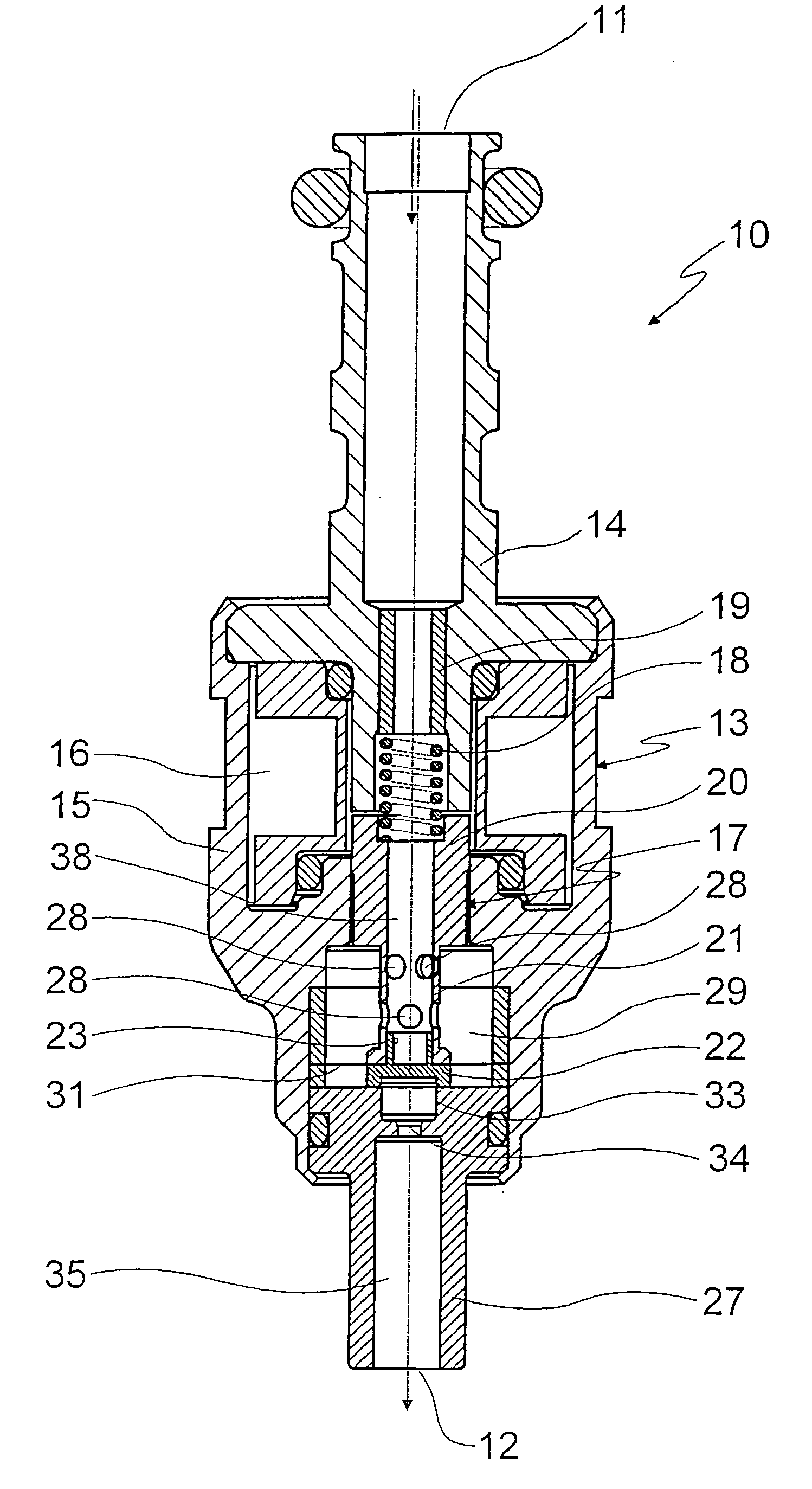
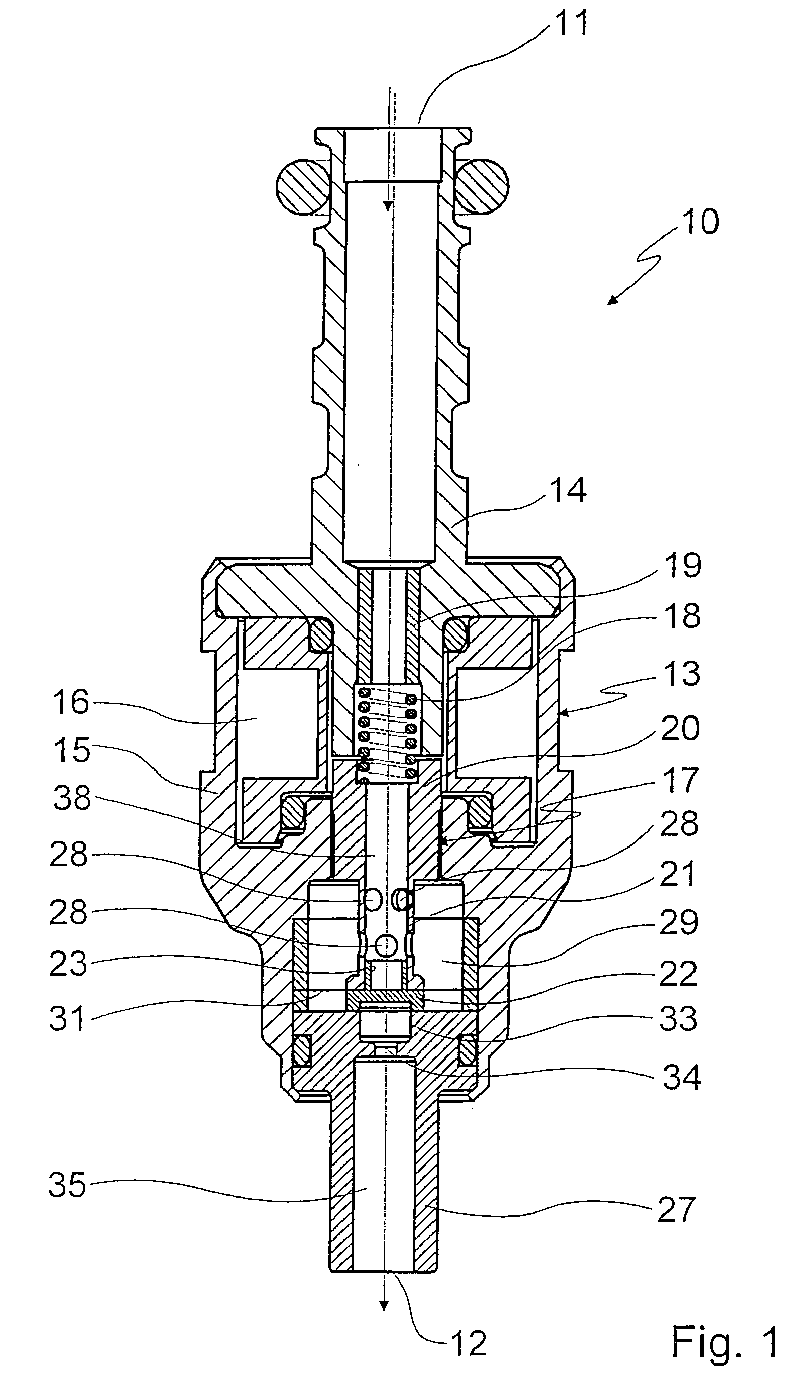
[0029]FIGS. 1 through 4 depict a gas valve 10 that is designed for use in a fuel cell or in a gas engine and that serves to regulate a flow of hydrogen or of natural gas (NG) from an inflow side 11 to an outlet side 12.

[0030] Gas valve 10 encompasses a multi-part housing 13 having a substantially tubular insert 14, on which inflow side 11 is configured and which is inserted axially, with a flange-like shoulder having an outside diameter enlargement, into a substantially hollow-cylindrical central valve body 15. Configured in central valve body 15 is a space 16 for an electromagnetic actuation unit that coacts with a valve armature 17 which is braced via a helical spring 18 against a sleeve 19 inserted into an inner orifice of insert 14.

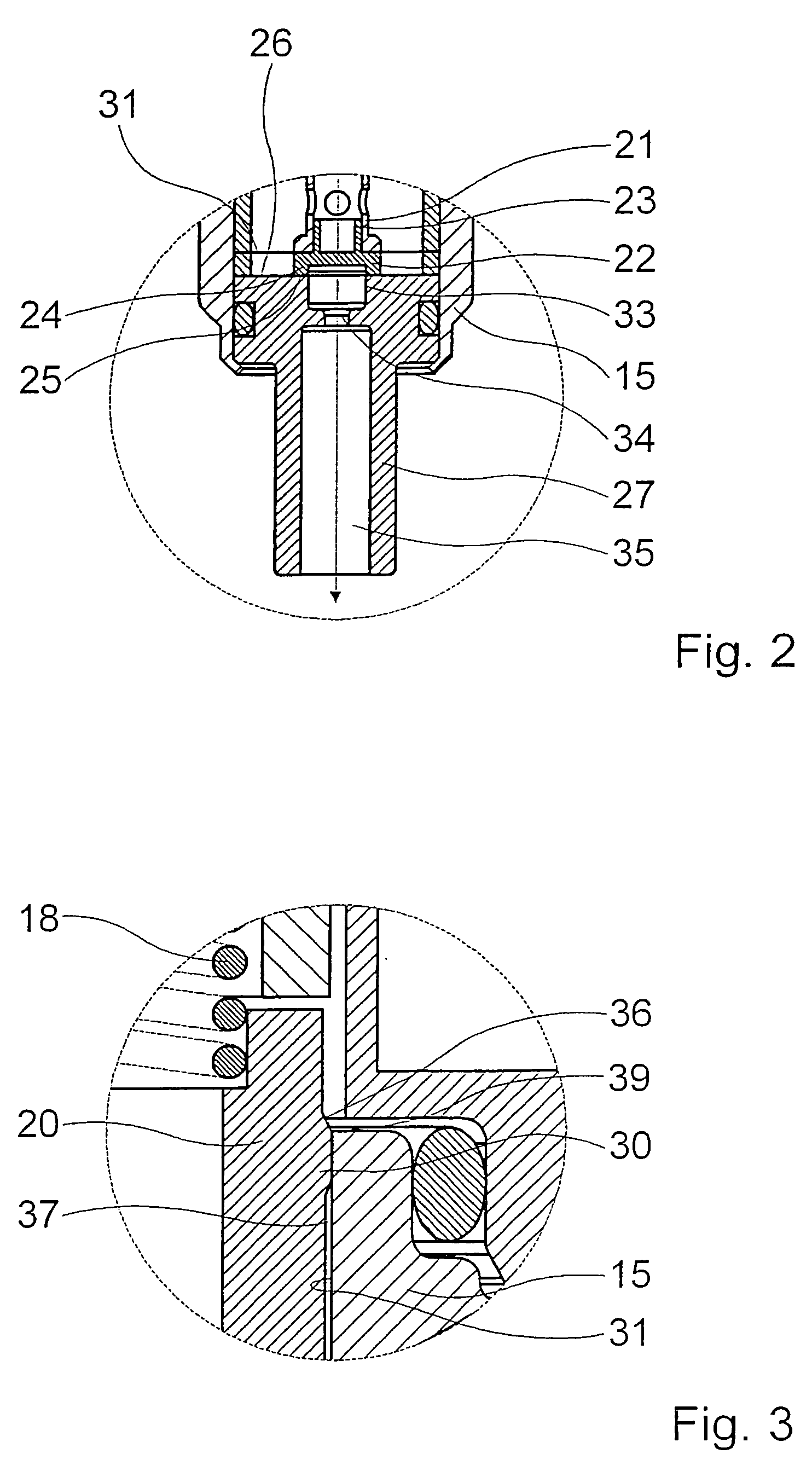
[0031] Valve armature 17 encompasses a region 20 of increased outside diameter as well as a region 21 of reduced outside diameter embodied in the manner of a constriction, adjacent to which at the end face is a valve closure member 22 that is insert...


PUM


Abstract

A valve for controlling a fluid, in particular for controlling a gas, is described, encompassing a valve housing an actuation unit for an at least locally tubular valve armature which is guided axially displaceably and is equipped with a valve closure member by which a fluid flow between an inflow side and an outlet side is controllable and which coacts with a valve seat. The valve armature comprises a guidance collar in a region remote from the valve closure member, and is equipped with a second guidance in a region offset with respect to the guidance collar.

Description

FIELD OF THE INVENTION [0001] The invention proceeds from a valve for controlling a fluid, in particular for controlling a gas. BACKGROUND INFORMATION [0002] A valve of this kind is known from practical use and is usable, for example, as a gas delivery valve in a spark-ignited engine, operated with natural gas (NG), of a motor vehicle. This valve designed for controlling a gas encompasses a valve housing in which a valve armature is axially displaceably guided. The valve armature, whose displacement can be triggered by way of an electromagnetic actuation unit, is equipped with a valve closure member which coacts with a valve seat and by which a fluid flow between an inflow side and an outlet side of the valve is controllable. [0003] In known gas valves of the kind described, the problem exists that when an oil-free gas is used, material wear occurs in the region of the valve armature and the valve seat because of the absence of lubrication, and that the valve armature can tilt and t...

Claims


Application Information

Patent Timeline
Patent Type & Authority Applications(United States)
IPC IPC(8): F16K31/02F02M21/02F16K31/06
CPCF16K31/0651F16K31/0655F02M21/0254F02M21/0266F02M21/0281Y02T10/32Y02T10/30
Inventor HANS, WALDEMARFAYE, IANBRENNER, FRANKMILLER, FRANKMAIER, MARTINBANTLEON, GUENTHERNGUYEN-SCHAEFER, THANH-HUNGHEBNER, THOMASKROEGER, KAI
Owner ROBERT BOSCH GMBH
Why Eureka
Try Eureka