
Motion control apparatus for teaching robot position, robot-position teaching apparatus, motion control method for teaching robot position, robot-position teaching method, and motion control program for teaching robot-position

a technology of robot position and teaching apparatus, applied in the direction of electric programme control, program control, instruments, etc., can solve the problem that the operation becomes and achieve the effect of reducing the burden of the teacher and improving the efficiency of the teaching operation

Inactive Publication Date: 2006-10-12
SEIKO EPSON CORP
View PDF3 Cites 25 Cited by
  • Summary
  • Abstract
  • Description
  • Claims
  • Application Information

AI Technical Summary

Benefits of technology

[0008] The present invention is devised in consideration of the above problems. An advantage of some aspects of the present invention is to provide a motion control apparatus and a robot-position teaching apparatus, for teaching a robot position, a motion control method and a robot-position teaching method, for teaching a robot position, a robot-position teaching method, and a motion control program for teaching a robot-position, in which an intuitional teaching operation based on an image capturing screen is made possible to reduce the burden of the teacher and improve the efficiency of the teaching operation.
[0010] The motion is controlled on the camera coordinate system and, therefore, the end point of the robot can be moved to the teaching preset position by an intuitional operating instruction based on the image capturing screen. As a consequence thereof, the burden of the teacher can be reduced. Further, the end point of the robot can be moved to the target position by a minimum and sufficient number of execution without unnecessary increase in the excution number of the operation instructions. Thus, the efficiency of the teaching can be improved. Furthermore, the operating error can be suppressed.
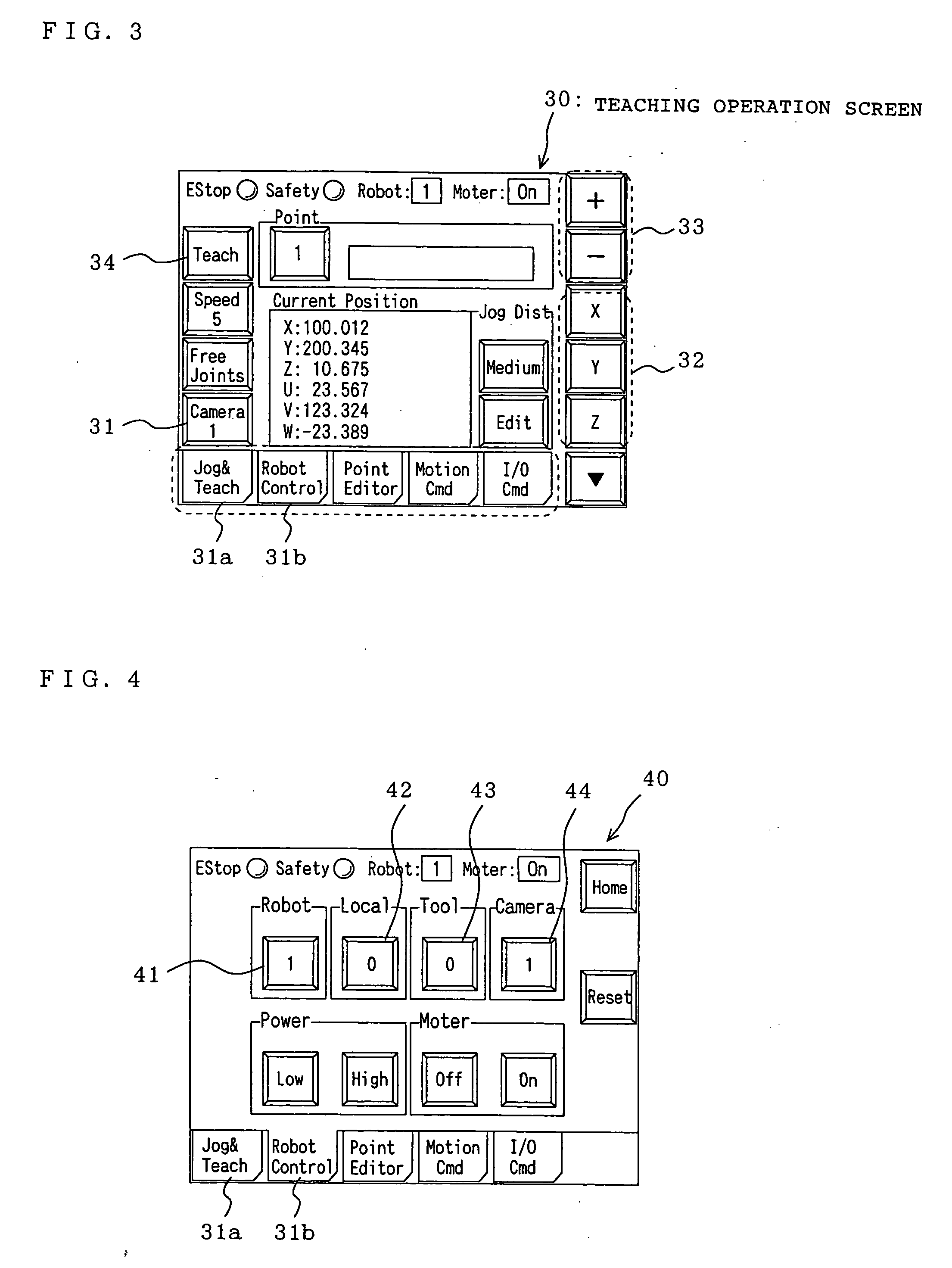
[0011] Further, in the motion control apparatus for teaching a robot position according to another aspect of the present invention, the operating means comprises operating-direction designating buttons that designate the x axis, the y axis, and the z axis on the camera coordinate system, and operating buttons that operate the robot end-point in the axial direction designated by the operating-direction designating button. As mentioned above, the operating instruction using the button operation facilitates the input operation of the operating command.
[0015] In addition, in the motion control apparatus for teaching a robot position according to a further aspect of the present invention, preferably, the teaching preset position is the position of the robot end-point at the time when a work as a working target is positioned in the center of the image capturing screen. In general, in the image captured by the camera, processing precision of the center on the screen is higher than that of the end on the screen. Therefore, the teaching position is set to the robot position at the time when the work position is in the center of the image capturing screen and, thus, this contributes to the operation of the work with high precision.
[0016] In addition, according to a further aspect of the present invention, there is provided a robot-position teaching apparatus comprising one of the above-mentioned motion control apparatuses for teaching the robot position. The robot-position teaching apparatus further comprises memory means that stores, as teaching data, attitude data of the robot at the time when the operating command is repeatedly input from the operating means and the end point of the robot reaches the teaching preset position. Thus, upon teaching the robot position, the end point of the robot can be moved to the teaching preset position with the motion control apparatus for teaching the robot position. As a consequence thereof, the teaching operation can be easily performed.

Problems solved by technology

As mentioned above, the teacher needs to perform the jog operation while recognizing the relationship between the robot coordinate system and the camera coordinate system, and this operation becomes the burden of the teacher.

Method used


Image

  • Motion control apparatus for teaching robot position, robot-position teaching apparatus, motion control method for teaching robot position, robot-position teaching method, and motion control program for teaching robot-position
  • Motion control apparatus for teaching robot position, robot-position teaching apparatus, motion control method for teaching robot position, robot-position teaching method, and motion control program for teaching robot-position
  • Motion control apparatus for teaching robot position, robot-position teaching apparatus, motion control method for teaching robot position, robot-position teaching method, and motion control program for teaching robot-position

Examples


Embodiment Construction

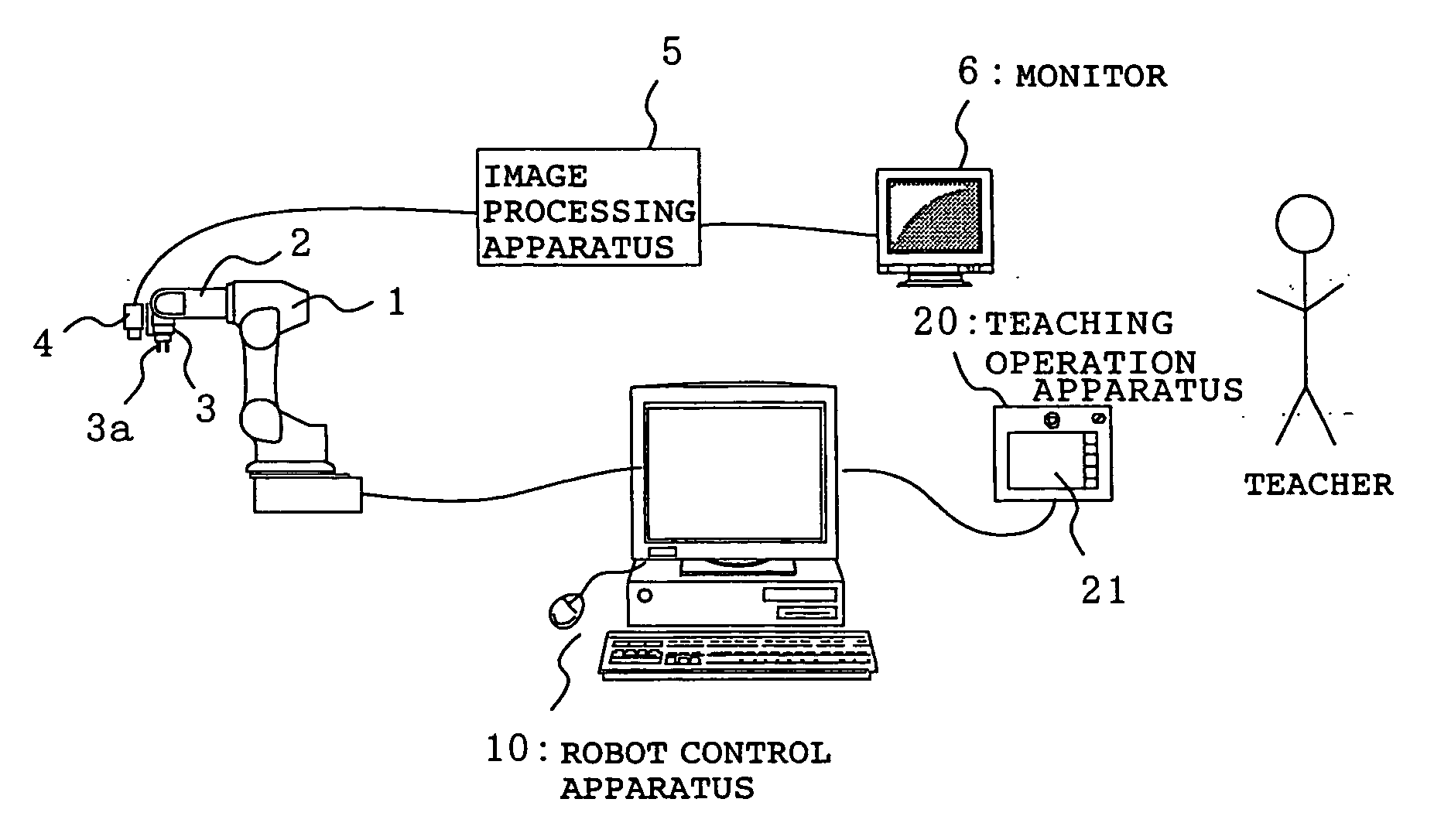
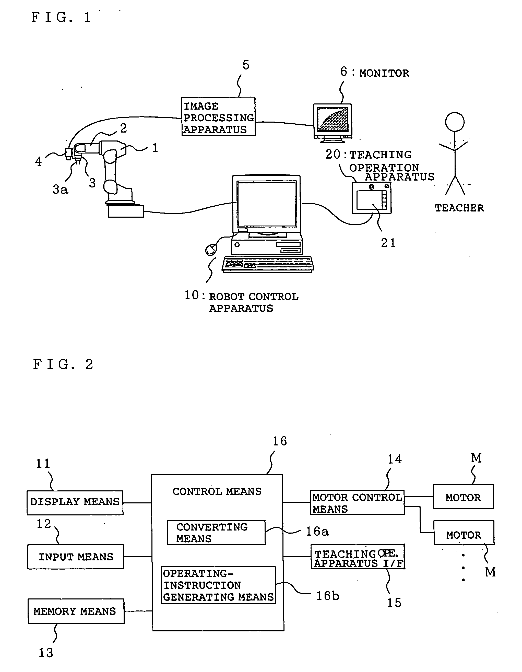
[0028]FIG. 1 is a diagram showing the entire structure of a robot system to which a motion control apparatus for teaching a robot position is applied according to an embodiment of the present invention.

[0029] A robot 1 comprises a multi-articulated robot having a plurality of joints according to the embodiment. An operating tool 3a capable of gripping a work, and a camera 4 that captures an image of the work are attached to a robot end-point 3 at the end of an arm 2. An image processing apparatus 5 processes the image captured by the camera 4 and a monitor 6 displays the image. Further, a robot control apparatus 10 that controls the robot 1 is connected to the robot 1, and a teaching operation apparatus 20 that performs teaching operation to the robot 1 is connected to the robot control apparatus 10. All the above-mentioned components constitute a robot system.

[0030] The teaching operation apparatus 20 comprises touch-panel display means 21 that displays a teaching operation scree...


PUM


Abstract

A motion control apparatus for teaching a robot position includes an operating unit that inputs an operating command to a robot on a camera coordinate system having, as a reference, an image capturing screen displayed on the monitor, a converting unit that generates a motion vector on the camera coordinate system for moving the robot from the current position to the next moving position in accordance with the operating command on the camera coordinate system input from the operating unit and converts the motion vector on the camera coordinate system into a motion vector on a robot coordinate system, an operating-instruction generating unit that generates a motor instructing value to be given to a motor arranged at a joint of the robot 1 based on the motion vector on the robot coordinate system obtained by the converting unit, and a motor control unit that controls the motor arranged at the joint of the robot in accordance with the motor instructing value generated by the operating-instruction generating unit.

Description

[0001] The entire disclosure of Japanese Patent Application No. 2005-110955, filed Apr. 7, 2005, is expressly incorporated by reference herein. BACKGROUND OF THE INVENTION [0002] 1. Field of the Invention [0003] The present invention relates to a technology suitable for operating of a robot to a teaching preset position while watching a captured image of a camera. [0004] 2. Description of the Related Art [0005] Conventionally, according to a robot-position teaching method, a robot comprises a camera, the camera captures an image of an inspection object, the captured image is subjected to image processing by an image processing apparatus, and the inspection object is inspected. Further, in an inspecting apparatus having an image display apparatus for displaying the image, a coordinate system of the robot is set in the image processing apparatus before teaching the robot, and the robot position is transmitted to the image processing apparatus from a robot controller during the teachin...

Claims


Application Information

Patent Timeline
Patent Type & Authority Applications(United States)
IPC IPC(8): G06F19/00B25J9/22G05B19/42
CPCB25J9/1697G05B19/425G05B2219/39057G05B2219/39442G05B2219/40003G05B2219/40523B25J9/10B25J9/16B25J13/00
Inventor SETSUDA, NOBUYUKI
Owner SEIKO EPSON CORP
Learn More