System and method for three-dimensional visualization of conductivity and current density distribution in electrically conducting object
a technology applied in the field of three-dimensional visualization of conductivity and current density distribution of electrically conducting objects, can solve the problems of poor image of eit, serious drawback of cdi technique, and methods that cannot visualize electrical properties of human bodies or substances. achieve the effect of more accurate high resolution
- Summary
- Abstract
- Description
- Claims
- Application Information
AI Technical Summary
Benefits of technology
Problems solved by technology
Method used
Image

Examples
first embodiment
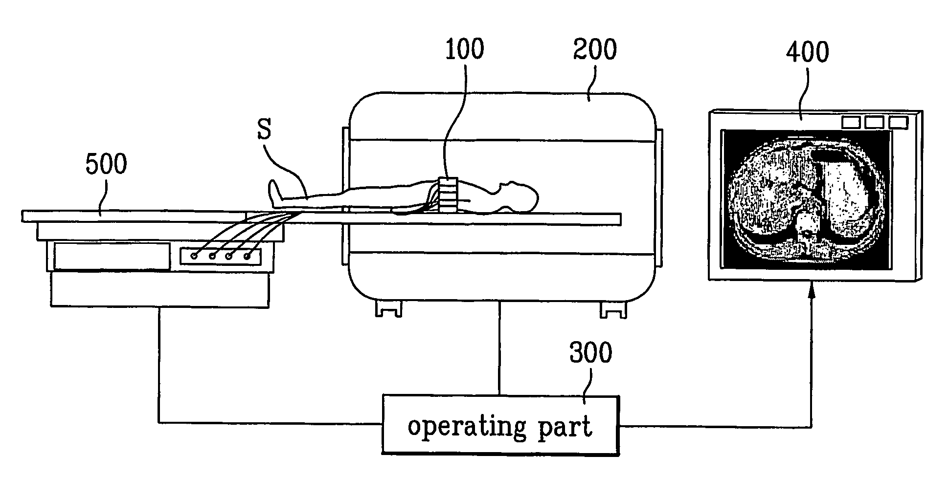
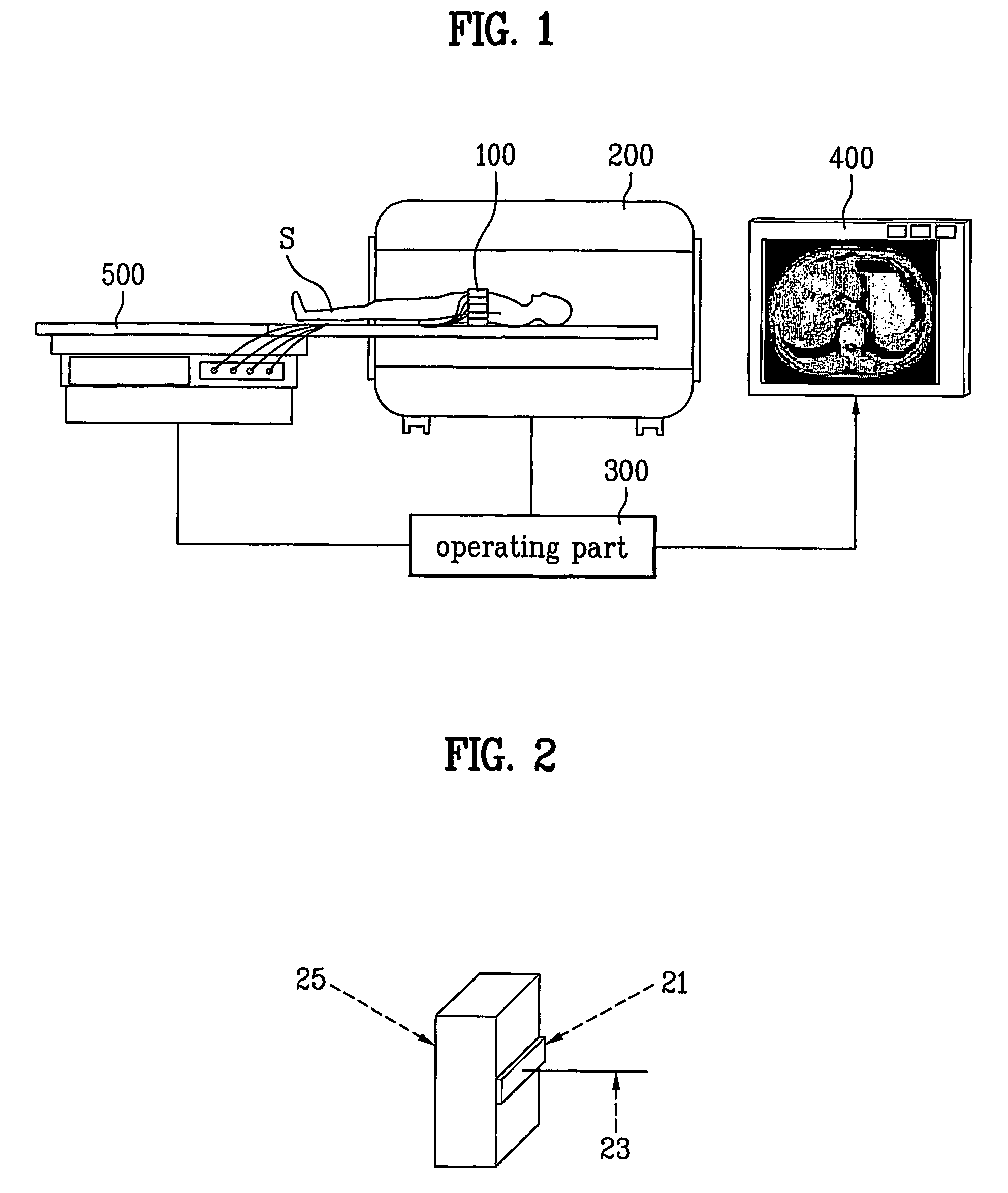
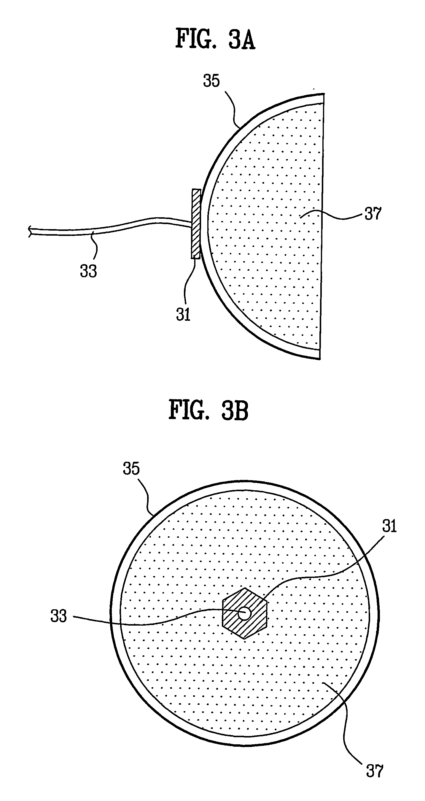
[0036] Referring to FIG. 1, a plurality of current injecting devices 100 are attached to a circumference of a measuring object ‘S’, i.e., a human body, and the measuring object ‘S’ is placed in an MRI scanner 200. In this instance, as described before, an insulating container 25 of the current injecting device 100 is stuffed with sponge having electrolyte gel or electrolyte solution absorbed therein.
[0037] Pairs of the current injecting devices 100 are selected one by one in succession, and a current Ij (j=1, 2, - - - , N) is supplied to an inside of the measuring object ‘S’ through the pair of the current injecting device 100 selected in succession. For an example, as shown in FIGS. 4A and 4B, in a case four current injecting devices 100a, 100b, 100c, and 100d are attached to a circumference of the measuring object ‘S’, the currents are supplied to the inside of the measuring object ‘S’ in two directions in succession. At first, a current I1 is supplied from the current injecting ...
second embodiment
[0067] A plurality of current injecting devices 100 are attached to a circumference of a measuring object ‘S’, i.e., a human body, and the measuring object ‘S’ is placed in an MRI scanner 200. In this instance, as described before, an insulating container of the current injecting device 100 is stuffed with sponge having electrolyte gel or electrolyte solution absorbed therein.
[0068] Pairs of the current injecting devices 100 are selected one by one in succession, and a current Ij (j=1, 2, - - - , N) is supplied to an inside of the measuring object ‘S’ through the pair of the current injecting device 100 selected in succession. For an example, as shown in FIG. 5, in a case four current injecting devices 100a, 100b, 100c, and 100d are attached to the circumference of the measuring object ‘S’, the current injecting devices can be paired in six cases for injecting the currents, such that the currents flow in six paths, and in six directions respectively under the control of the operati...
PUM
| Property | Measurement | Unit |
|---|---|---|
| current flow | aaaaa | aaaaa |
| conductivity | aaaaa | aaaaa |
| current density | aaaaa | aaaaa |
Abstract
Description
Claims
Application Information
 - R&D
- Intellectual Property
- Life Sciences
- Materials
- Tech Scout
- Unparalleled Data Quality
- Higher Quality Content
- 60% Fewer Hallucinations
Browse by: Latest US Patents, China's latest patents, Technical Efficacy Thesaurus, Application Domain, Technology Topic, Popular Technical Reports.
© 2025 PatSnap. All rights reserved.Legal|Privacy policy|Modern Slavery Act Transparency Statement|Sitemap|About US| Contact US: help@patsnap.com