Light emitting device and electronic device
a technology of light emitting devices and electronic devices, applied in the field of organic light emitting devices, can solve problems such as reducing contrast or disturbing display images, and achieve the effect of suppressing contrast and preventing disturbance of displayed images
- Summary
- Abstract
- Description
- Claims
- Application Information
AI Technical Summary
Benefits of technology
Problems solved by technology
Method used
Image
Examples
embodiment 1
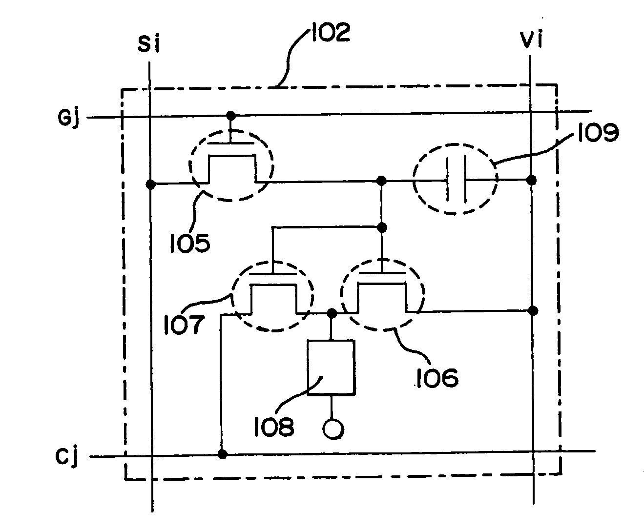
[0093] In this embodiment, the case where the light emitting device of the present invention as shown in FIGS. 1A and 1B is driven by a digital gradation system will be described using FIG. 6.
[0094] First, a potential of the counter electrode of the OLED is kept to be the same potential as a power source potential of the power source line. Then, the scan line G1 is selected by a selection signal inputted from the scan line driver circuit 104. As a result, the switching TFTs 105 of all pixels (pixels in the first line) connected with the scan line G1 become an on state.
[0095] Then, digital video signals of a first bit are inputted from the signal line driver circuit 103 to the signal lines (S1 to Sx). The digital video signals are inputted to the gate electrodes of the driver TFTs 106 and the gate electrodes of the discharging TFTs 107 through the switching TFT 105s.
[0096] Switchings of the driver TFTs 106 and the discharging TFTs 107 are controlled by information indicating 1 or ...
embodiment 2
[0111] A structure of a pixel in the light emitting device of the present invention is not limited to the structure shown in FIG. 1B. In this embodiment, an example of a structure of a pixel in the light emitting device of the present invention, which is different from the structure shown in FIG. 1B, will be described. FIGS. 7A, 7B, 17A, and 17B show structures of a pixel in this embodiment.
[0112] A pixel shown in FIG. 7A includes at least one first signal line Sai, at least one second signal line Sbi, at least one first scan line Gaj, at least one second scan line Gbj, at least one power source line Vi, and at least one discharge line Cj.
[0113] Also, the pixel shown in FIG. 7A further includes a first switching TFT 705a, a second switching TFT 705b, a driver TFT 706, a discharging TFT 707, an OLED 708, and a storage capacitor 709.
[0114] Next, the connection among respective elements and wirings in the pixel shown in FIG. 7A will be described in more detail.
[0115] The gate elect...
embodiment 3
[0159] Next, described with reference to FIGS. 8A to 12 is a method of forming the light emitting device of the present invention. Here, the method of simultaneously forming, on the same substrate, the switching TFT and the driver TFT of the pixel portion, and the TFTs of a driver portion provided surrounding the pixel portion is described in detail according to steps. Further, the method of forming the discharge TFT is not illustrated to simplify the explanation, because the discharge TFT can be formed by reference of manufacturing method of forming the switching TFT and the driver TFT.
[0160] This embodiment uses a substrate 900 of a glass such as barium borosilicate glass or aluminoborosilicate glass as represented by the glass #7059 or the glass #1737 of Corning Co. There is no limitation on the substrate 900 provided it has a property of transmitting light, and there may be used a quartz substrate. There may be further used a plastic substrate having heat resistance capable of ...
PUM
 Abstract
Description
Claims
Application Information
 - R&D
- Intellectual Property
- Life Sciences
- Materials
- Tech Scout
- Unparalleled Data Quality
- Higher Quality Content
- 60% Fewer Hallucinations
Browse by: Latest US Patents, China's latest patents, Technical Efficacy Thesaurus, Application Domain, Technology Topic, Popular Technical Reports.
© 2025 PatSnap. All rights reserved.Legal|Privacy policy|Modern Slavery Act Transparency Statement|Sitemap|About US| Contact US: help@patsnap.com


