
Dental implant

a technology of dental implants and pins, applied in dental prosthetics, dental surgery, medical science, etc., can solve the problems of increased psychological and economic burden of patients, two operations are needed, and patients must endure inconvenience for a long time, so as to improve the initial bone recovery reaction, improve the pin type structure, and maximize the coupling with bone tissue

Inactive Publication Date: 2006-09-28
MEGAGEN IMPLANT
View PDF5 Cites 28 Cited by
  • Summary
  • Abstract
  • Description
  • Claims
  • Application Information

AI Technical Summary

Benefits of technology

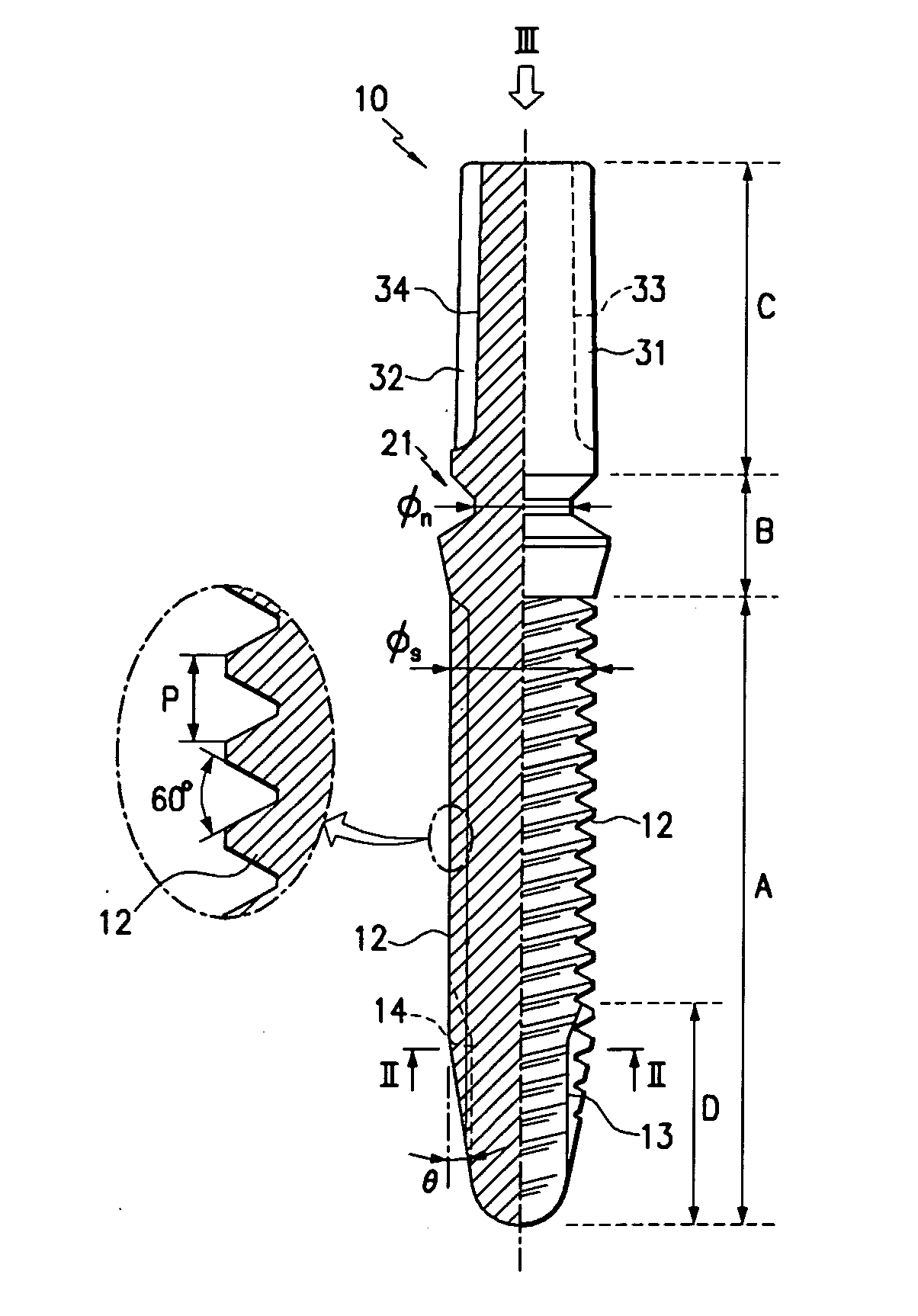
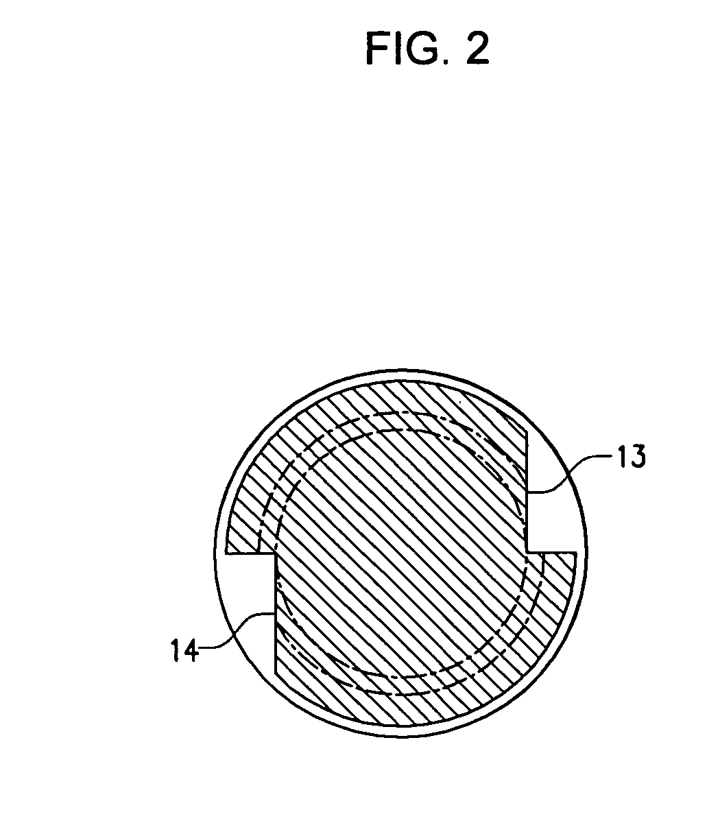
The present invention provides an implant that can be embedded in a jawbone and act as an artificial tooth root to which a dental prosthesis can be connected. The implant has a fixture portion, a neck portion, and an abutment portion. The fixture portion is embedded in the jawbone and has a screw thread on its outer surface. The neck portion is integrally formed on the upper end of the fixture portion and is bendable. The abutment portion is integrally formed on the upper end of the neck portion and has a cylindrical shape extending upwardly. The implant is designed to maximize coupling with bone tissue, improve the initial bone recovery reaction, and effectively disperse stress during chewing. The implant has an improved embedded portion that maintains its height after chewing. The screw thread has a pitch of 0.6 mm and a pitch angle of 60 degrees. The diameter of the neck is less than the average diameter of the fixture portion. The abutment portion has at least one insertion groove that is symmetrical with respect to the center axis of the fixture portion. The bottom surface of the insertion groove is tapered to decrease the thickness of the fixture portion at the bottom.

Problems solved by technology

Therefore, the second type of implant has an aesthetic advantage over the first type of implant, but has a disadvantage that two operations are needed.
Therefore, there is a problem that patients must endure inconvenience for a long time after embedding the implant.
In addition, a disadvantage of the two-stage operations is that psychological and economic burdens of a patient are increased because of the two operations, and the operation process is complicated.
Efforts have been made to eliminate the second operation by connecting the final dental prosthesis to the implant during the first operation and there have been reports of success of such efforts, but complexities in the process of using tools for connection of the final dental prosthesis have only been improved a little bit due to improvements in design of the implant, and as such, complexities still remain.

Method used


Image

  • Dental implant
  • Dental implant
  • Dental implant

Examples


Embodiment Construction

[0026] Embodiments of the present invention will now be explained such that those skilled in the art may easily execute the present invention.

[0027] Preferred embodiments of the present invention will now be described in detail with reference to the accompanying drawings.

[0028]FIG. 1 is a partial sectional view of an implant according to an embodiment of the present invention, FIG. 2 is a sectional view along a line II-II in FIG. 2, and FIG. 3 is a top view shown from a direction of III.

[0029] As illustrated in FIG. 1, an implant10 according to an embodiment of the present invention includes a fixture portion A, a neck portion B, and an abutment portion C.

[0030] The fixture portion A that is positioned at a lower portion of the implant 10 is inserted into a tissue of a jawbone, and has screw threads 12 on an outer circumferential surface thereof. The fixture portion A having the screw threads 12 is inserted into a drilled hole formed in a jawbone. The screw threads 12 are prefer...


PUM


Abstract

A dental implant comprises a fixture portion, a neck portion, and an abutment portion. The fixture portion is embedded in a jawbone. The fixture has a screw thread on an outer circumferential thereof. The neck portion is integrally formed on an upper end of the fixture portion and has a neck that is formed to be narrow such that the neck is bendable. The abutment portion is integrally formed on an upper end of the neck portion and has a cylindrical shape extending upwardly.

Description

BACKGROUND OF THE INVENTION [0001] (a) Field of the Invention [0002] The present invention relates to an artificial tooth system, and more particularly, to a dental implant having a fixture that is embedded in a jawbone and an abutment to which a dental prosthesis is mounted. [0003] (b) Description of the Related Art [0004] The term “dental implant” means a device for forming artificial teeth by inserting a metallic component having the shape of a tooth into a portion of a jawbone where teeth have been eliminated, maintaining the metallic component in place while new bone grows around the metallic component, and then mounting an artificial tooth to the metallic component. Types of implants can be divided into a under-periosteum type of implant, an inter-bone type of implant, a bone-passing type of implant, and the like, according to an embedded position thereof; and a screw-shaped implant, a cylindrically-shaped implant, and the like, according to an outer shape of the implant. Such...

Claims


Application Information

Patent Timeline
Patent Type & Authority Applications(United States)
IPC IPC(8): A61C8/00A61C13/00
CPCA61C8/0022A61C8/0024A61C8/0075A61C8/00A61C13/00
Inventor PARK, KWANG-BUM
Owner MEGAGEN IMPLANT
Learn More