Liquid crystal device and electronic equipment
a technology of liquid crystal and electronic equipment, which is applied in the direction of instruments, artificial islands, constructions, etc., can solve the problem that the crystal device cannot perform semi-transmissive reflective display, and achieve the effect of high-quality display
- Summary
- Abstract
- Description
- Claims
- Application Information
AI Technical Summary
Benefits of technology
Problems solved by technology
Method used
Image
Examples
first embodiment
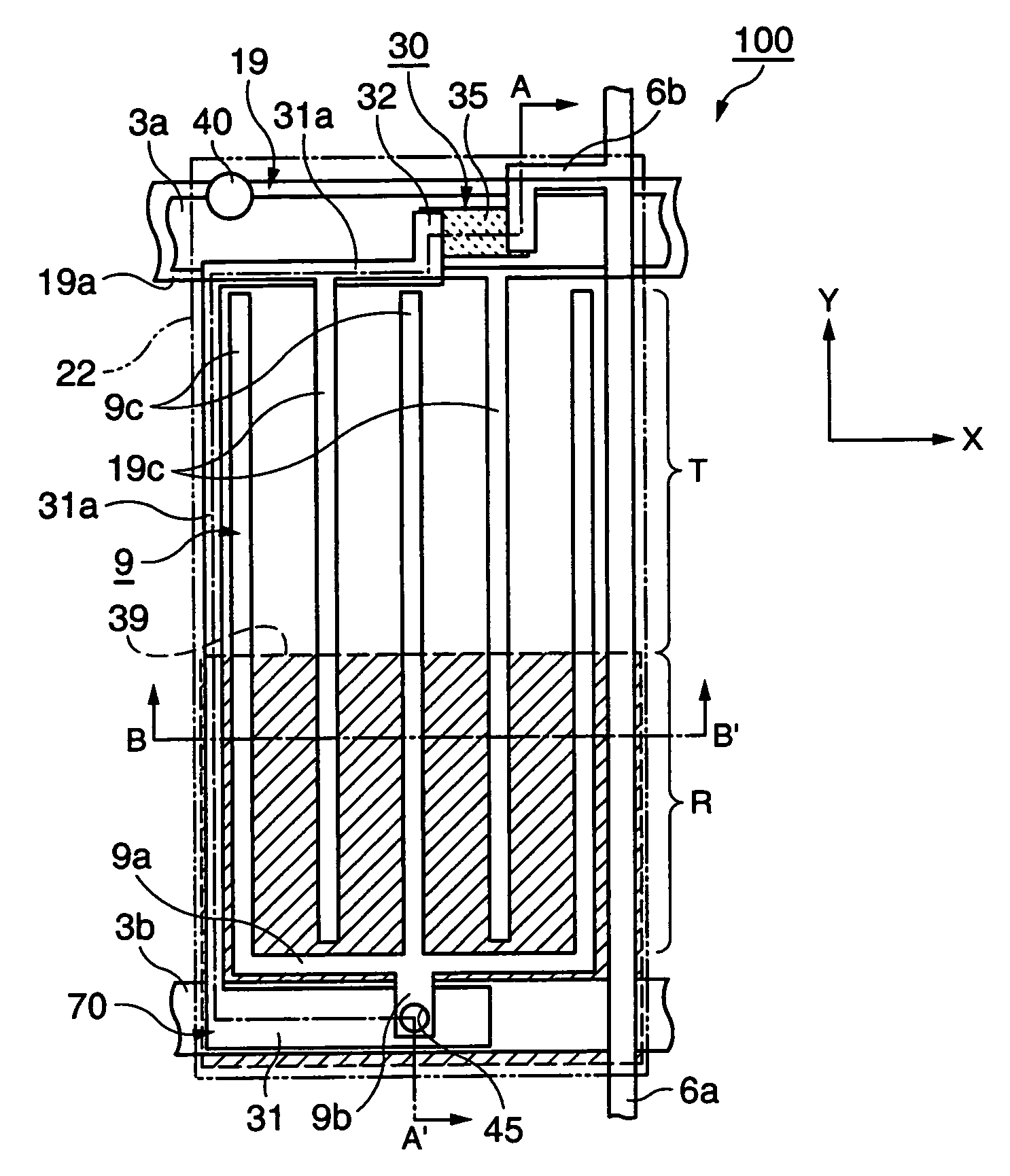
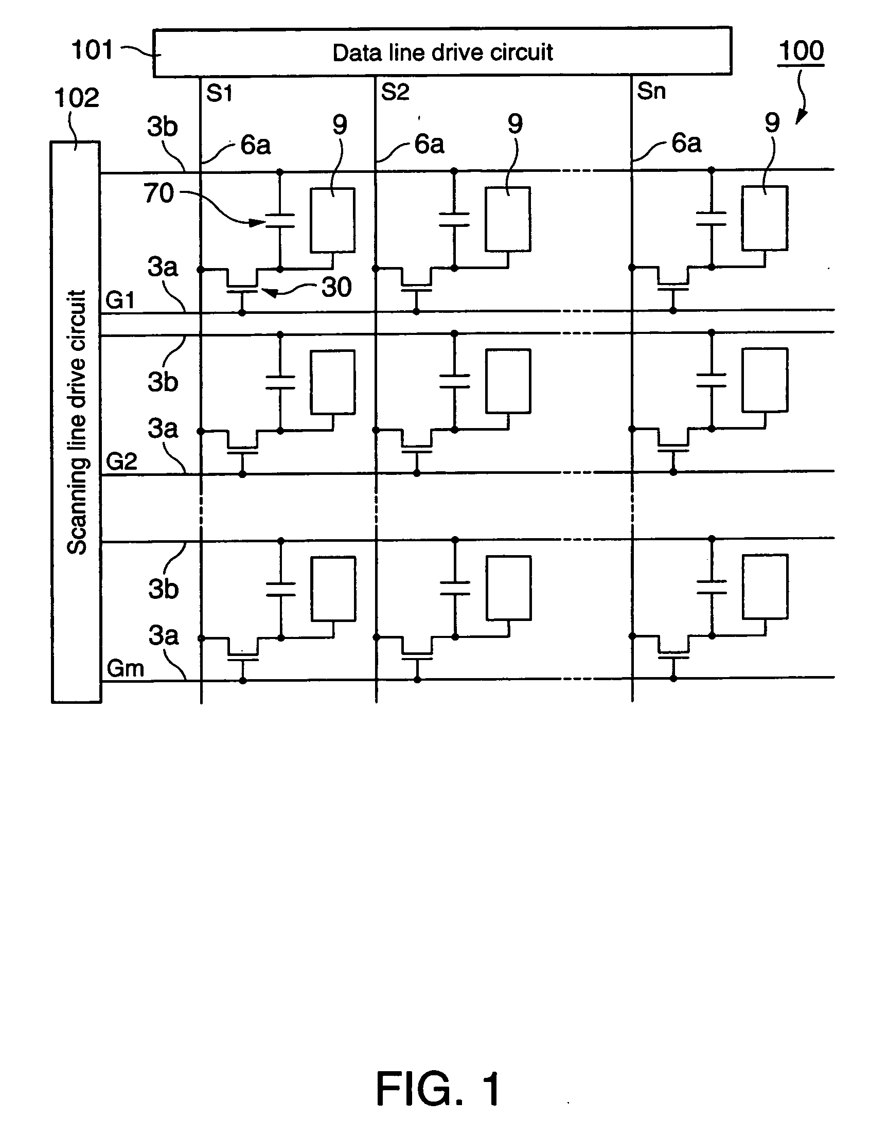
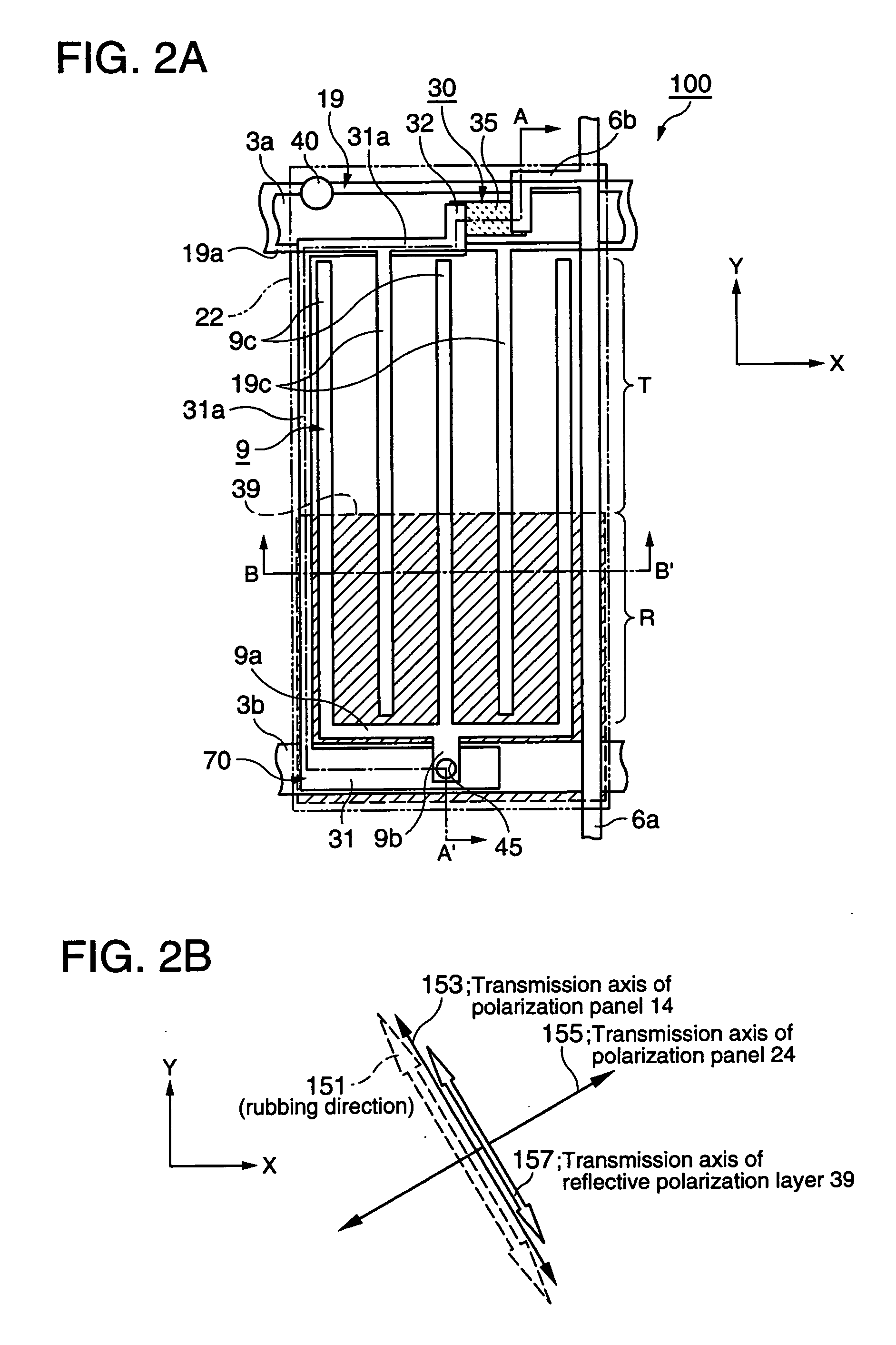
[0068] A liquid crystal device according to a first embodiment of the invention will be described hereinafter with reference to the accompanying drawings. The liquid crystal device according to the first embodiment of the invention is a liquid crystal device adopting an in-plane switching (IPS) mode, which is a kind of horizontal electric field mode in which an electric field is applied to a liquid crystal in the substrate surface direction, i.e., a horizontal electric field is applied to the liquid crystal, to control the orientation of the liquid crystal, whereby picture display is performed.
[0069] Also, the liquid crystal device according to the first embodiment of the invention is a color liquid crystal device having a color filter on a substrate wherein three dots that output three colored lights, such as red, green, and blue, respectively, constitute a pixel. Consequently, a display region having the smallest display unit is referred to as “a sub-pixel region,” and a display ...
second embodiment
[0111] Now, a liquid crystal device according to a second embodiment of the invention will be described with reference to FIGS. 8 to 12.
[0112]FIG. 8 is a circuit diagram of the liquid crystal device 200 according to the second embodiment of the invention including a plurality of sub-pixel regions arranged in the shape of a matrix. FIG. 9A is a plan view showing an arbitrary sub-pixel region of the liquid crystal device 200 according to the second embodiment of the invention, and FIG. 9B is a view showing the arrangement of optical axes of the arbitrary sub-pixel region of the liquid crystal device 200 according to the second embodiment of the invention. FIG. 10 is a sectional view taken along line D-D′ of FIG. 9A.
[0113] The liquid crystal device 200 according to the second embodiment of the invention is an active matrix type liquid crystal device using thin film diode (TFD) elements as the pixel switching elements. Also, the liquid crystal device 200 according to the second embodi...
third embodiment
[0147] Now, a liquid crystal device according to a third embodiment of the invention will be described with reference to the associated drawings. The liquid crystal device according to the third embodiment of the invention is a liquid crystal device adopting a fringe field switching (FFS) mode, which is a kind of horizontal electric field mode in which an electric field is applied to a liquid crystal in the substrate surface direction, i.e., a horizontal electric field is applied to the liquid crystal, to control the orientation of the liquid crystal, whereby picture display is performed. Also, the liquid crystal device according to the second embodiment of the invention is a color liquid crystal device having a color filter on a substrate wherein three dots that output three colored lights, such as red, green, and blue, respectively, constitute a pixel. Consequently, a display region having the smallest display unit is referred to as “a sub-pixel region,” and a display region inclu...
PUM
| Property | Measurement | Unit |
|---|---|---|
| angle | aaaaa | aaaaa |
| width | aaaaa | aaaaa |
| thickness | aaaaa | aaaaa |
Abstract
Description
Claims
Application Information
 - R&D
- Intellectual Property
- Life Sciences
- Materials
- Tech Scout
- Unparalleled Data Quality
- Higher Quality Content
- 60% Fewer Hallucinations
Browse by: Latest US Patents, China's latest patents, Technical Efficacy Thesaurus, Application Domain, Technology Topic, Popular Technical Reports.
© 2025 PatSnap. All rights reserved.Legal|Privacy policy|Modern Slavery Act Transparency Statement|Sitemap|About US| Contact US: help@patsnap.com


