
Gas discharge lamp power supply

a technology of power supply and gas discharge lamp, which is applied in the direction of cathode-ray/electron beam tube circuit elements, cathode-ray/electron beam tube details, casings/cabinets/drawers, etc., and can solve problems such as difficult to see, potentially dangerous ground fault currents, and not easily accessibl

Inactive Publication Date: 2006-09-28
FRANCESCOTT FETZER
View PDF14 Cites 6 Cited by
  • Summary
  • Abstract
  • Description
  • Claims
  • Application Information

AI Technical Summary

Benefits of technology

[0010] The present invention provides a gas discharge lamp power supply that is more convenient to install and service. The gas discharge lamp power supply of the present invention presents electrical terminals, a service or test switch and an indicator light so that they are more accessible and visible to an installer or service person. The gas discharge lamp power supply of the present invention is especially useful in those applications where the power supply itself is difficult to access, for example, where the power supply is located in an electrical raceway.
[0011] The gas discharge lamp power supply of the present invention further has improved fault diagnosing capabilities and can substantially improve the quality of power supply service in the field. The gas discharge lamp power supply is able to display a diagnosed power supply fault condition after line power has been removed and then reconnected and thus, is especially useful when the power supply is experiencing an intermittent fault condition.
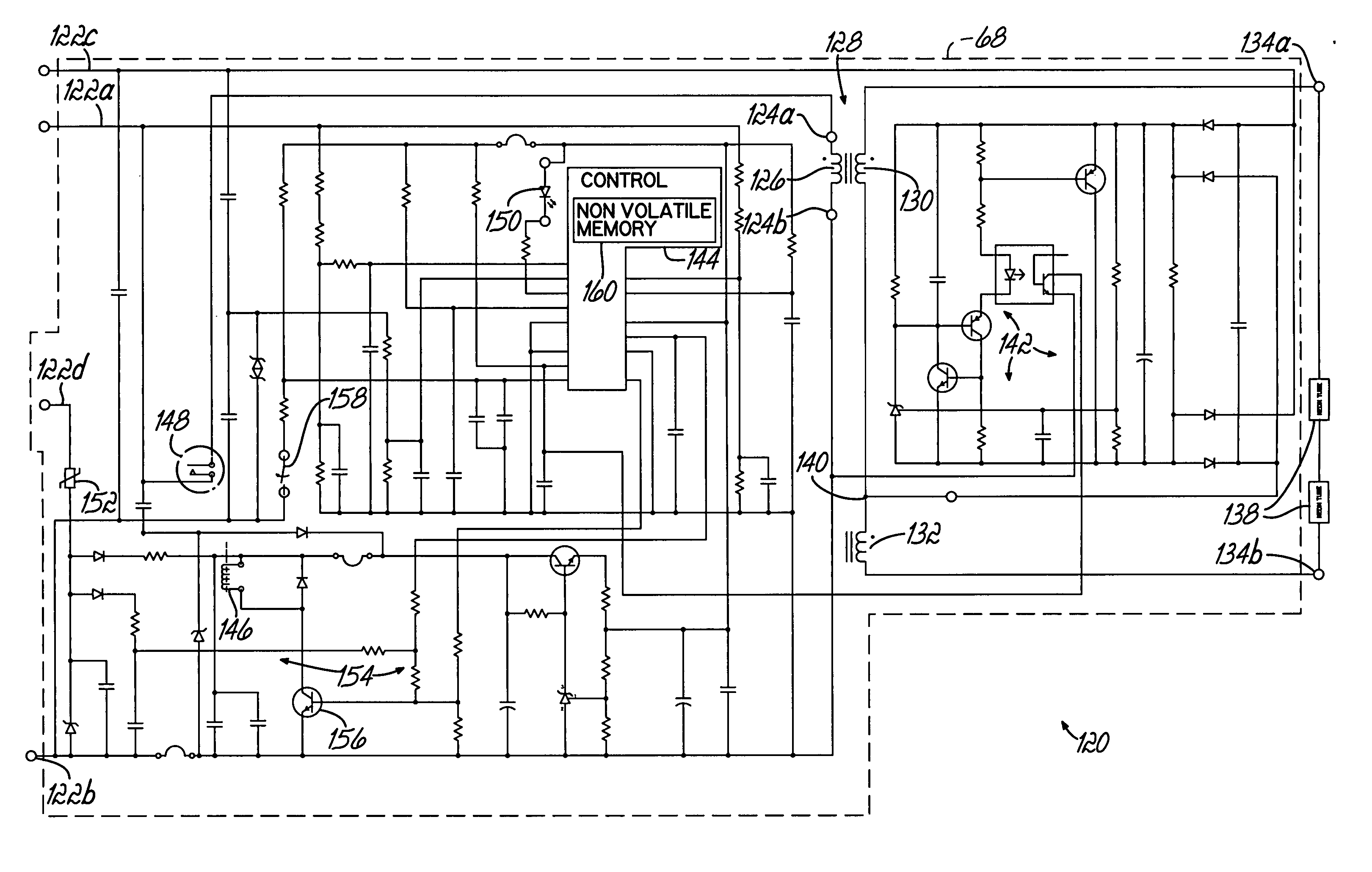
[0013] In another embodiment, the gas discharge lamp power supply has a fault detection circuit that provides an error signal in response to detecting a fault condition, and a control with a nonvolatile memory for storing an error code in response to the error signal. An error indicator is connected to the control and is activated by the control in response to the error signal. Storage of the error code in the nonvolatile memory permits the LED to display the error code upon power being removed from and then, subsequently reapplied, to the power supply.

Problems solved by technology

The power supply 20 is often placed at locations that are not immediately adjacent to the neon tubing and often are not easily accessible.
Further, the LED 48 also being on a vertical end wall is difficult to see and may require some determination on the part of a service person to view.
Thus, the gas discharge lamp power supply 20, when placed in an electrical raceway, that itself may not be readily accessible, presents various challenges to service personnel in attempting to troubleshoot and repair the power supply.
A concern with known neon sign power supplies is that a potentially dangerous ground fault current may occur anytime there is a relatively low impedance path from one of the high voltage output leads of the neon power supply to ground.
Other concerns with known neon sign power supplies are that an installer or service person may inadvertently reverse the line power connections to the low voltage input terminals of the power supply, or an equipment ground may be improperly connected.
In this example, the power supply will function normally for some period of time but will then fail.
As previously noted, troubleshooting a neon sign for ground faults and other problems is difficult because often the power supply may be located in a building attic area or an electrical raceway, which makes the power supply hard to view and access.
Further, in such a location, improper and / or poor connections and ground faults are rarely visibly detectable and servicing the power supply is difficult.
However, upon approaching a power supply with a reported malfunction, experience, intuition and training cause a service person to first remove line power prior to any handling, visual inspection or other service activity.
However, upon removing the line power, the error code stored in the power supply is lost and the visual indicator is turned off.
Therefore, the value of the power supply's self diagnostic capability of generating and displaying an error code is lost.
Again, the usefulness of the power supply's self diagnostic capability is lost.
Without any guidance as to the source of the problem, especially an intermittent one, the neon sign can experience extended periods of no illumination and downtime.

Method used


Image

  • Gas discharge lamp power supply
  • Gas discharge lamp power supply
  • Gas discharge lamp power supply

Examples


first embodiment

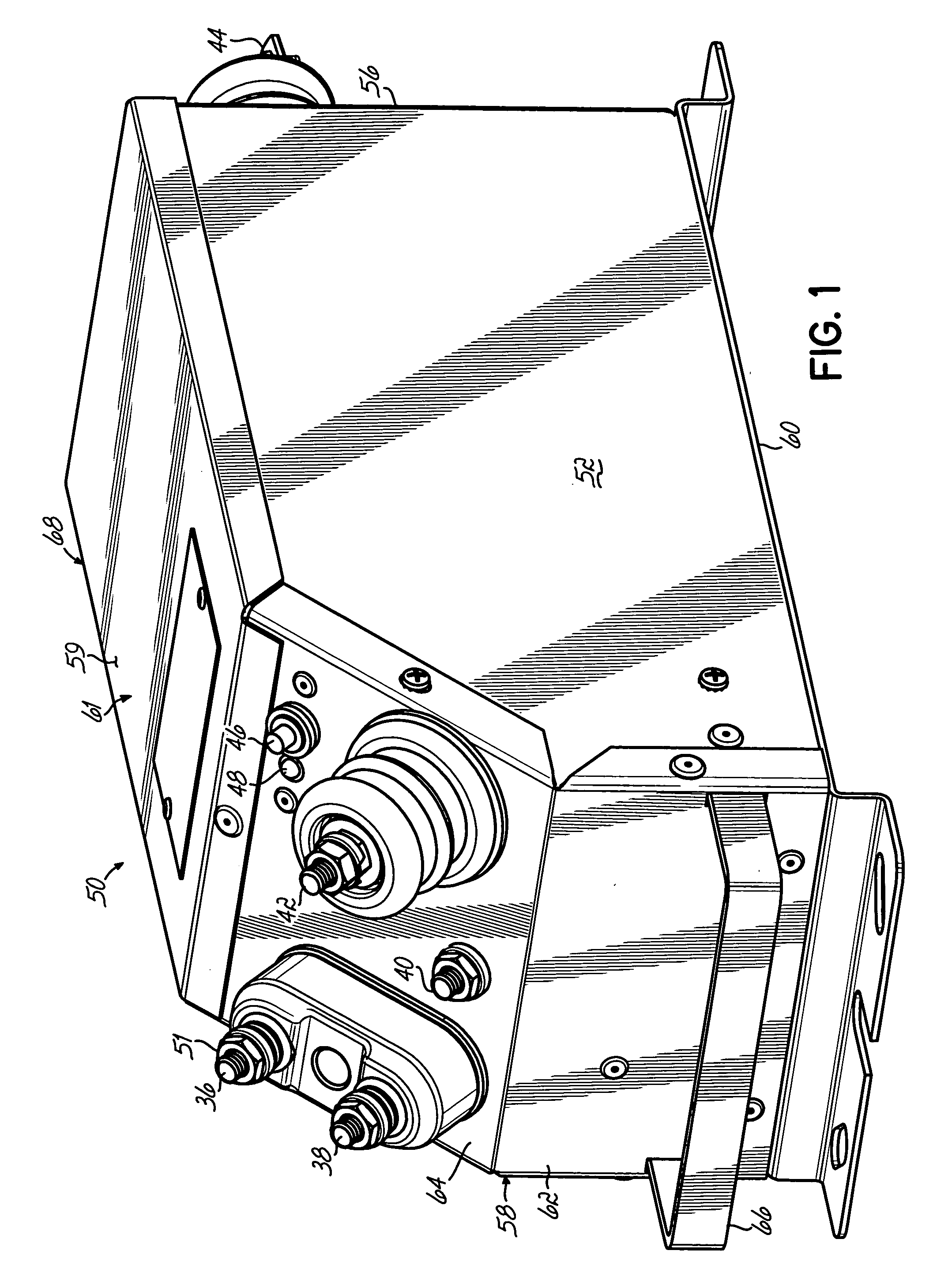
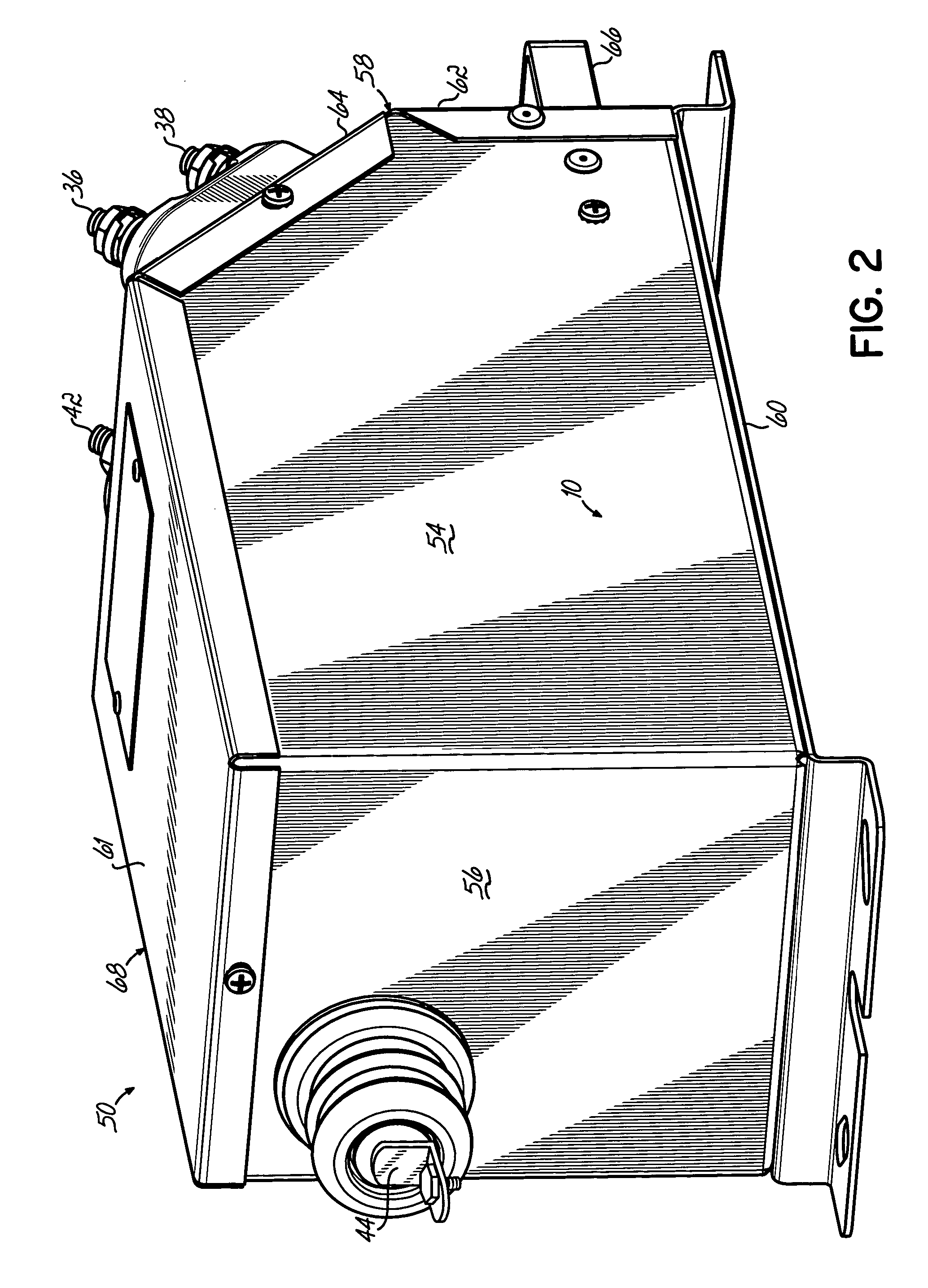
[0030] Referring to FIGS. 1 and 2, in a first embodiment, a gas discharge lamp power supply 50 has a pair of opposed side walls 52, 54 and a pair of opposed end walls 56, 58. The walls 52-56 extend from, and are substantially mutually perpendicular to, the base 60 and are substantially mutually perpendicular to each other. The end wall 58 has a first, lower wall 62 that extends from, and is substantially perpendicular to, the base 60 and the side walls 52, 54. The end wall 58 further has a second, sloped wall 64 that is angled with respect to the base 60, for example, at 45 degrees. However, the sloped wall 64 can have any angle that maintains ends of the terminals 36-44 and associated securing nuts below a plane of a major surface 59 of a cover 61. The cover 61 extends between the walls 52, 54, 56, 64. The base 60, walls 52-58 and cover 61 are fastened together to form an enclosure or housing 68 that contains a transformer and power supply circuit as shown in FIG. 14. It is intende...

second embodiment

[0031] Referring to FIGS. 3 and 4, in a second embodiment, a gas discharge lamp power supply 50a has a housing 68 substantially identical to the housing 68 of the power supply 50 shown in FIGS. 1 and 2. However, with the power supply 50a, only the low voltage input terminals 36-40, switch 46 and LED 48 are mounted on the sloped wall 64 of end wall 58. Both of the high voltage input terminals 42, 44 are mounted on the opposite end wall 56.

[0032] Referring to FIGS. 5 and 6, in a third embodiment, a gas discharge lamp power supply 50b has a pair of substantially parallel, opposed side walls 70, 72 that are substantially perpendicular to base elements 74. In the third embodiment, each of the end walls 58, 76 is comprised of respective lower walls 62, 78 that are substantially mutually perpendicular to the side walls 70, 72. In addition, each of the end walls 58, 76 has respective upper, angled or sloped walls 64, 80 that intersect with the side walls 70, 72. A cover 82 extends between t...

third embodiment

[0036] a handle for the power supply 50 is illustrated in FIGS. 10A-10C. In this embodiment, the handle 92 is mounted in the opposing side walls 52, 54 at a location immediately below upper edges of the side walls 52, 54 and below the cover 61. In this embodiment, the handle 92 is often located longitudinally at a location immediately above a center of gravity of the power supply 50, so that, when the power supply is lifted, the weight of the power supply is balanced, that is, equally distributed on both sides of the handle 92.

[0037] Referring to FIG. 11, in another embodiment, a handle is made of a strap 100 that extends lengthwise and is connected at its ends to the sloped walls 64, 80. The attachment points 102, 104 of the ends of the handle 100 are selected such that the weight of the power supply 50 is equally distributed on both sides of the handle 100.

[0038] A gas discharge lamp power supply circuit that may be used with any of the embodiments of FIGS. 1-11, as well are othe...


PUM


Abstract

A gas discharge lamp power supply having a base, a pair of opposed side walls extending from the base, and opposed first and second end walls extending from the base between the opposed side walls. The first end wall has a sloped wall extending angularly between the side walls, and two input terminals are mounted on the sloped wall. In another embodiment, the power supply has a control with a nonvolatile memory for storing an error code in response to a detected fault condition, thereby permitting the error code to be displayed upon power being removed from and then, subsequently reapplied.

Description

FIELD OF THE INVENTION [0001] The present invention relates generally to gas discharge lamps and, more particularly, to a gas discharge lamp power supply. BACKGROUND OF THE INVENTION [0002] One example of a gas discharge lamp is neon tubing, which is often used in signage. Although the following discussion will refer to transformers used for neon tubing or signs, it will be understood that principles of the present invention have application to transformers for other gas discharge tube lamps as well. Power supplies for neon signs use a transformer to convert a low impedance, low voltage power source, for example, a known 60 Hz AC line power having a line voltage in a range of about 100-250 Volts (“VAC”), to a higher voltage source, for example, 15 KiloVolts, suitable for illuminating the neon sign. The 120 Volt AC line power is connected to a low voltage primary winding of the transformer and the high voltage secondary winding of the transformer is connected to the neon sign. [0003]...

Claims


Application Information

Patent Timeline
IPC IPC(8): H01J13/46
CPCH05B41/00
Inventor HOPKINS, WILLIAM T.BANKS, ANTHONY W.SMITH, ALAN M.PICKVET, LOUIS B.TOWE, ROBERT L.SCHLEMM, CHARLES A.
Owner FRANCESCOTT FETZER
Learn More