
Fiber optic monitor for railroad switch

a fiber optic monitor and switch technology, applied in railway signalling and safety, roads, construction, etc., can solve the problems of high wear-out rate, inherently high maintenance device, and often lacking complete position information of the dispatcher

Inactive Publication Date: 2006-09-28
FIBERA
View PDF6 Cites 17 Cited by
  • Summary
  • Abstract
  • Description
  • Claims
  • Application Information

AI Technical Summary

Benefits of technology

[0008] Accordingly, it is an object of the present inventio...

Problems solved by technology

The dispatchers thus often lack complete position information for the trains that are about to pass respective railroad switches because there is no current device being widely used to monitor for this.
Railroad switches are inherently high maintenance devices, with high wear-out rates.
Nonetheless, many incidents of failure still occur during the intervals between routine inspections.
For example, the wear on them varies considerably, often due to factors that are unpredictable or not easily monitored.
These problems were ones such as those noted, as well as others such as snow or rubbish clogging contacts (causing derailment), ballast structure changes, and wrong direction switch setting.
It follows that insuring the proper operation of railroad switches is still not a well developed art, and that new and improved systems for this will provide substantial benefits in railway safety.

Method used


Image

  • Fiber optic monitor for railroad switch
  • Fiber optic monitor for railroad switch
  • Fiber optic monitor for railroad switch

Examples


Embodiment Construction

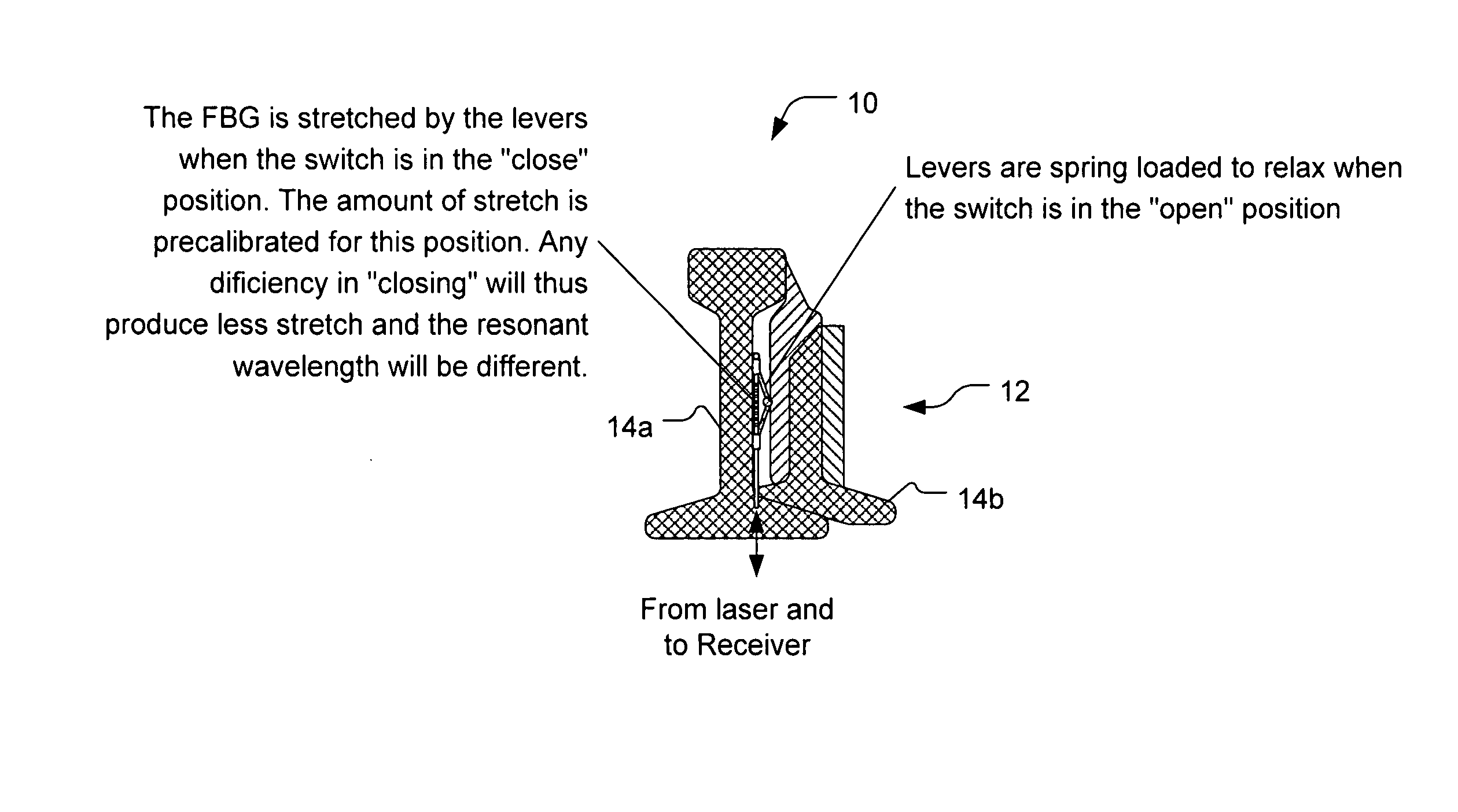
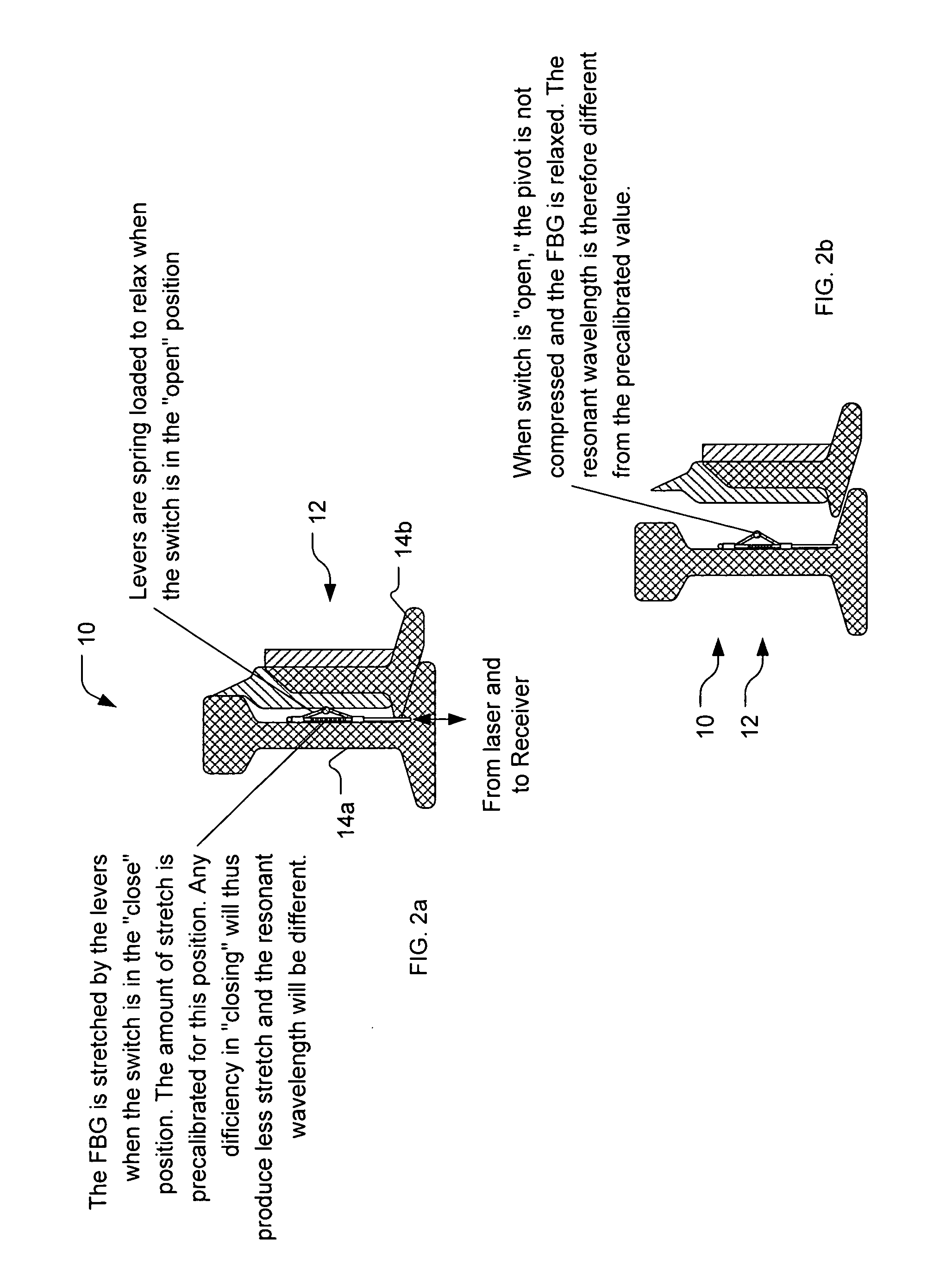
[0020] A preferred embodiment of the present invention is a fiber optic monitor for railroad switches. As illustrated in the various drawings herein, and particularly in the views of FIGS. 2a-b and FIGS. 3a-c, preferred embodiments of the invention are depicted by the general reference character 10.

[0021] In this invention, we propose to use fiber Bragg grating (FBG) sensors to monitor railway track conditions and the contact of railroad switches. The applicable physics for FBGs has been described elsewhere, including in widely available optics texts and in patent applications related to railway operations and safety by the present inventor, and therefore is not discussed in great detail herein. In brief, an FBG exhibits a resonant condition whereby it reflects light of a particular wavelength. As stress is applied to or removed from the FBG, the resonant wavelength changes. Accordingly, by providing suitable light and monitoring for changes in which wavelengths are (or are not) re...


PUM


Abstract

An improved railroad switch monitoring unit of the type that determines whether a mobile rail is brought into a closed state or an open state with respect to a stationary rail. The improvement comprises a fiber Bragg grating (FBG) included in the monitoring unit that is used to determine, based on stress able change in the resonant wavelength of the FBG, whether the mobile rail and the stationary rail are closed or open.

Description

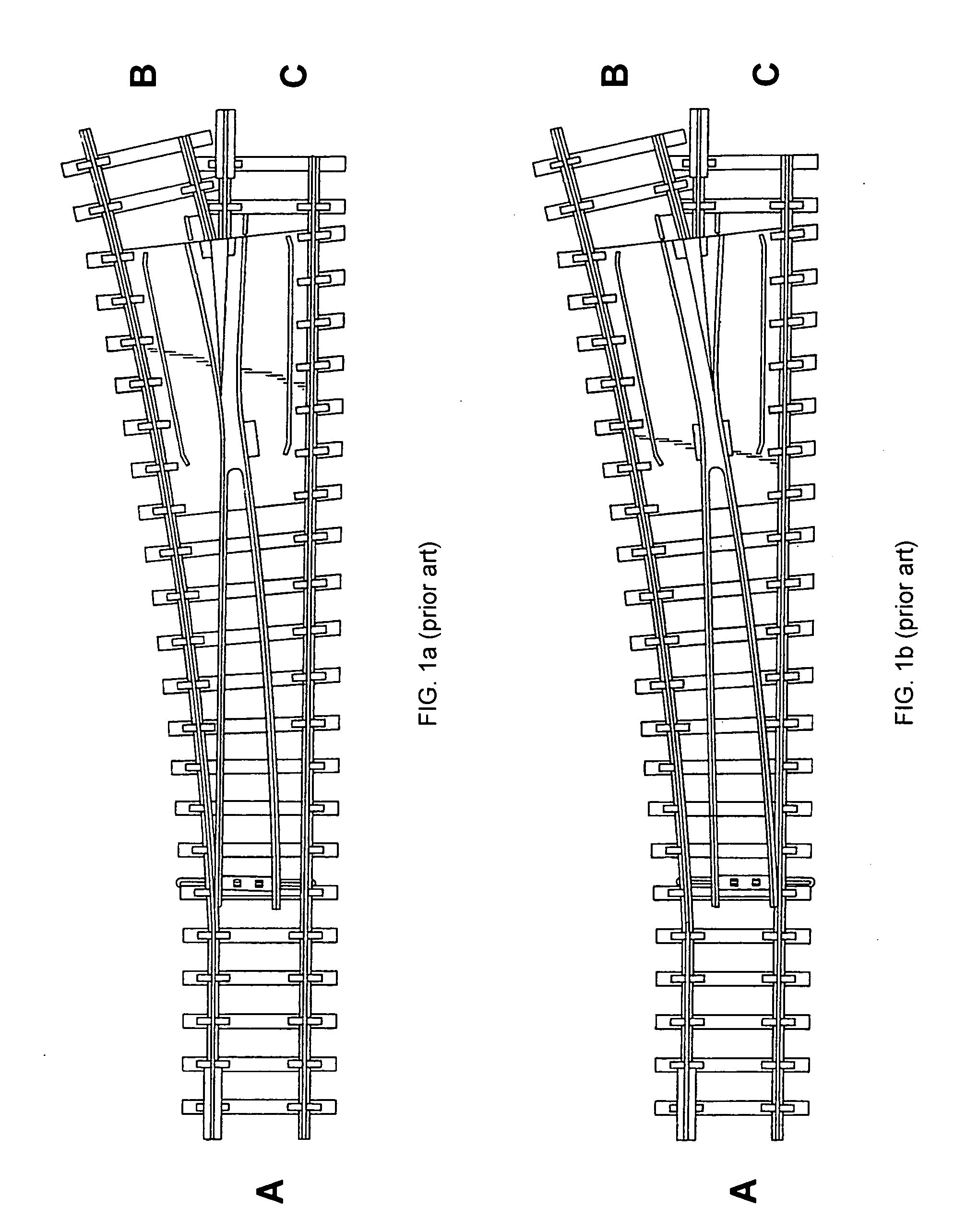
CROSS-REFERENCE TO RELATED APPLICATIONS [0001] This application claims the benefit of U.S. Provisional Application No. 60 / 594,292, filed Mar. 25, 2005, hereby incorporated by reference in its entirety.TECHNICAL FIELD [0002] The present invention relates generally to railway safety, and more particularly to such in railroad track switches or turnouts. BACKGROUND ART [0003] The railroad switch, also commonly called a “turnout,” is an important device for railroad operations. It enables trains to move from main to branch lines (or vice versa), and allows dispatchers to schedule operations. FIGS. 1a-b (prior art) show an example of a typical railroad switch, connecting A and C in FIG. 1a and connecting A and B in FIG. 1b. [0004] Railroad switches have historically been operated manually, but are now usually operated electronically by dispatchers in control rooms that can be quite far away from the actual railroad switch locations. The dispatchers thus often lack complete position inform...

Claims


Application Information

Patent Timeline
IPC IPC(8): E01B7/02
CPCB61L5/107
Inventor TSAI, JOHN C.
Owner FIBERA
Learn More