
Environmental chamber and ultrasonic nebulizer assembly therefor

a technology of ultrasonic nebulizer and environment chamber, which is applied in the direction of liquid spraying apparatus, mixing, chemical equipment and processes, etc., can solve the problems of difficult to precisely and reliably control the relative humidity within the chamber, and achieve efficient humidification of the chamber air and precise and reliable control of the relative humidity

Active Publication Date: 2006-09-28
BARNSTEAD THERMOLYNE
View PDF25 Cites 35 Cited by
  • Summary
  • Abstract
  • Description
  • Claims
  • Application Information

AI Technical Summary

Benefits of technology

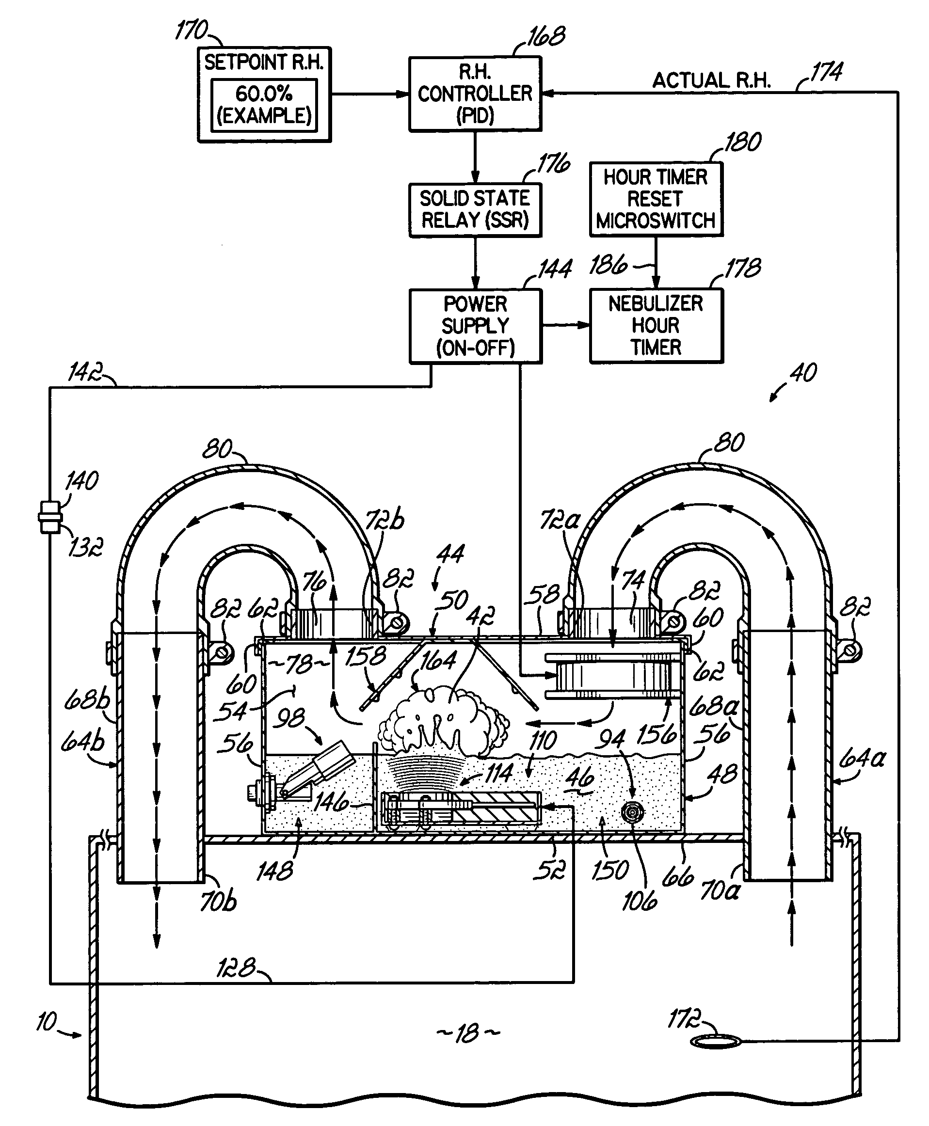
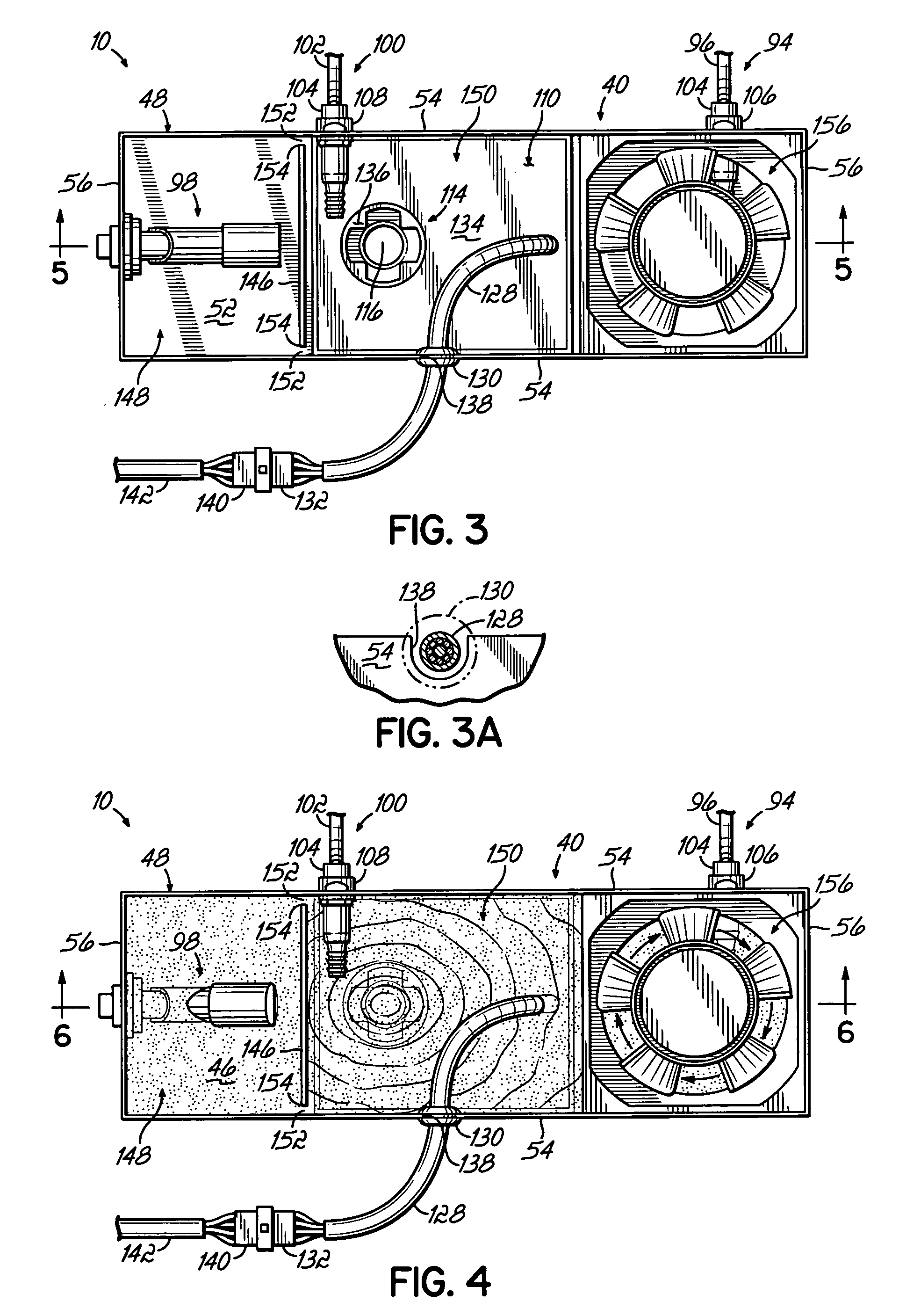
[0008] In accordance with the principles of the present invention, an environmental chamber having an enclosed internal chamber is provided with a humidification system in the form of an ultrasonic nebulizer assembly. In one embodiment, the ultrasonic nebulizer assembly is connected in closed-loop fluid communication with the enclosed chamber so that a closed-loop air flow path is provided between the ultrasonic nebulizer assembly and the enclosed chamber. The ultrasonic nebulizer assembly is configured to generate water vapor, preferably having water droplets in the micron range, and introduce the water vapor into the enclosed chamber for controlling the relative humidity within the chamber.
[0016] The environmental chamber and ultrasonic nebulizer assembly of present invention provide for precise and reliable control of the relative humidity within the chamber. The environmental chamber and ultrasonic nebulizer assembly of present invention also provide for efficient humidification of the chamber air without causing undesirable accumulation of water droplets within the chamber.

Problems solved by technology

Conventional spray nozzles and atomizers used in known environmental chambers typically form water droplets that are not uniform in size so that both smaller and larger water droplets are mixed with the forced air introduced into the enclosed chamber.
The larger water droplets are not readily absorbed by the air within the chamber so that it is oftentimes difficult to precisely and reliably control the relative humidity within the chamber at a predetermined relative humidity set-point.
Also, the larger droplets have a tendency to accumulate on the walls of the enclosed chamber and eventually the droplets form a puddle of water on the floor of the chamber which is undesirable.

Method used


Image

  • Environmental chamber and ultrasonic nebulizer assembly therefor
  • Environmental chamber and ultrasonic nebulizer assembly therefor
  • Environmental chamber and ultrasonic nebulizer assembly therefor

Examples


Embodiment Construction

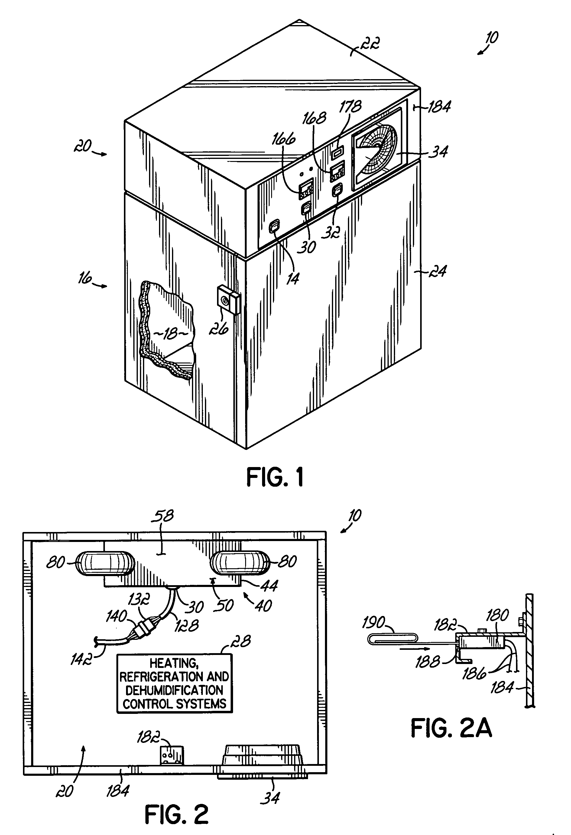
[0029] Referring to the figures, and to FIG. 1 in particular, an environmental chamber 10 is shown in accordance with one embodiment of the present invention. Environmental chamber 10 is connected to a power source 12 (FIGS. 8 and 9) and is activated by the user through a front panel power switch 14. As will be described in greater detail below, the environmental chamber 10 is designed to provide accurate environmental control of temperature and relative humidity within the chamber 10 for use, by way of example, in ICH pharmaceutical stability testing, genetic studies, chromatography tests, tissue culture studies and other research and development applications such as shelf life tests and packaging, paper products or electronic component breakdown.

[0030] According to one aspect of the present invention, the environmental chamber 10 includes a lower chamber section 16 having an enclosed internal chamber 18 (FIG. 1) made of stainless steel or other suitable material and an upper cont...


PUM


Abstract

An environmental chamber includes an ultrasonic nebulizer assembly for controlling the relative humidity within the chamber. The ultrasonic nebulizer assembly is connected in closed-loop fluid communication with an enclosed chamber of the environmental chamber and includes an ultrasonic nebulizer module to generate water vapor that is introduced into the enclosed chamber. The ultrasonic nebulizer module is constructed to be immersed in water within the ultrasonic nebulizer assembly and is readily replaceable by the user. A nebulizer hour timer is provided to monitor the length of time of the ultrasonic nebulizer is operating to provide a precise indication to the user of how much life is left in the ultrasonic nebulizer before it needs to be replaced.

Description

FIELD OF THE INVENTION [0001] The present invention relates generally to humidification systems and, more particularly, to a humidification system for use in an environmental chamber to control the relative humidity within the environmental chamber during testing of products within the chamber. BACKGROUND OF THE INVENTION [0002] Environmental chambers are designed to provide accurate environmental control of temperature and relative humidity within the chamber for use in ICH pharmaceutical stability testing, genetic studies, chromatography tests, tissue culture studies and other research and development applications such as shelf life tests and packaging, paper products or electronic component breakdown, for example. Environmental chambers typically include a heating and refrigeration control system to control the temperature within the enclosed internal chamber and a humidification system to control the relative humidity within the chamber. The products placed within the enclosed c...

Claims


Application Information

Patent Timeline
IPC IPC(8): A61M11/00B05B17/06
CPCB05B17/0615Y10S261/48
Inventor MURRAY, MICHAEL LOUISSTONE, BRADLEY WILLIAM
Owner BARNSTEAD THERMOLYNE
Learn More