
Material systems and methods of three-dimensional printing

a three-dimensional printing and material system technology, applied in the direction of additive manufacturing processes, manufacturing tools, wood veneer joining, etc., can solve the problems of slow method, high cost of selective laser sintering process, and less expensive binder printing equipmen

Active Publication Date: 2006-09-21
3D SYST INC
View PDF99 Cites 134 Cited by
  • Summary
  • Abstract
  • Description
  • Claims
  • Application Information

AI Technical Summary

Benefits of technology

[0015] The present invention is directed to improved materials systems and methods for producing appearance models, small numbers of functional parts, etc. in an office environment.

Problems solved by technology

The selective laser sintering process is expensive due to the high cost of the laser and the complexity of the equipment used.
In addition, only one laser is used at a time, making it a slow method.
In addition, the liquid binder printing equipment is much less expensive than the laser equipment due to the high cost of the laser and the high cost of the related beam deflection optics and controls.
The liquid binder printing technique has a serious reliability problem associated with the spray nozzles becoming clogged with the binder and / or powder material.
Clogging occurs when binders having high levels of suspended solids are used.
The problem with clogging requires frequent interruptions of the build in order to clean the spray nozzle.
The clogging problem increases the time and labor required to build parts and to maintain the equipment.
Therefore, although the liquid binder printing technique represents an advance in speed and cost over the selective laser sintering process, it suffers from reliability problems that slow down the build rate, increasing labor and equipment maintenance costs.
This problem interferes with the potential speed advantage of increased printing capability presented by the plurality of spray nozzles.
In addition to the above-mentioned disadvantages, the powders, especially metallic powders, used in both selective laser sintering and liquid binder techniques present safety issues that render them undesirable for use in an office environment.
These safety issues may require special clothing and processing facilities to prevent, for example, skin contact or inhalation of toxic materials.
In addition, more expense may be incurred through complying with regulations for the disposal of toxic materials.
For these reasons, these techniques do not lend themselves to being used in typical office environments, such as architectural and design firms, or doctors' offices.

Method used


Image

  • Material systems and methods of three-dimensional printing
  • Material systems and methods of three-dimensional printing
  • Material systems and methods of three-dimensional printing

Examples


example 1

[0130] Line tests were performed to determine suitable combinations of anionic starch, cationic starch, and polyelectrolyte. A particulate material was prepared to include a cationic starch and an anionic starch blended in a 1:1 mixture, by weight. A fluid mixture containing an aqueous binder and about 3% of a polyelectrolyte was prepared and dispensed onto the powder. A syringe was used to squirt the polyelectrolyte mixture onto the starch mixture. Suitable material systems are shown below in Table 1.

TABLE 1LineCationicAnionicTestStarchStarchPolyelectrolyteResultsApollo 4280Astro Gum 3010PMAA−PAA−PSS++PDAC−Pencat 600Astro Gum 3010PMAA−PAA−PSS++PDAC−Apollo 4280Astro Gum 21PMAA+PAA−PSS++PDAC−Pencat 600Astro Gum 21PMAA+PAA−PSS++PDAC−

[0131] Those material system combinations with positive results were further tested on a three-dimensional printing system. Those material systems with negative results were further optimized.

example 2

[0132] Line tests were performed on a material system in which the particulate material was glass beads having an aminosilane coupling agent on the exterior surface. The fluid material was an aqueous solution containing about 2% potassium sulfate and about 3% of either PMAA or PAA (as shown below in Table 2). The pH of the fluid was adjusted to about 5 by adding a 1 Molar solution of sodium hydrogen sulfate. A syringe was used to squirt the fluid mixture onto the particulate mixture.

[0133] The composition of the particulate mixture and fluid mixture are shown below in Table 2. The resulting lines were cohesive and were lifted out of the bed of glass beads without breaking.

TABLE 2BeadGlass beadsDiameter (μm)PolyelectrolyteSpheriglass, 2530-CP-0371PMAA71PAASpheriglass, 2227-CP-03119PMAA119PAA

example 3

[0134] Test bars were formed to evaluate the strength of a material system. ZB7™ stock binder from Z Corporation was printed onto a particulate mixture. The particulate mixture included polyanionic polystyrene sulfonate (PSS) (MW 70,000, available from Aldrich Chemicals, Milwaukee, Wis.) and a polycationic potato starch (available under the product name Unicat C3T from Kalamazoo Paper Chemicals, Kalamazoo, Mich.), and glass beads (available under the product name Spheriglass #2530(CP-03) and #2227(CP-03) from Potter Industries) or technical grade pumice (available from PTI Process Chemicals, Cary, Ill.). The glass beads were unreactive with the PSS, potato starch, and the aqueous fluid.

[0135] An electrostatic attraction between the PSS and starch was activated by the fluid, causing the materials to interact chemically to form an essentially solid article that included the glass beads or the pumice.

TABLE 3Glass BeadPumiceUnicatDiameterParticle diameterPSSC3T(μm)(μm)525701268237909...


PUM

PropertyMeasurementUnit
mean diameteraaaaaaaaaa

Abstract

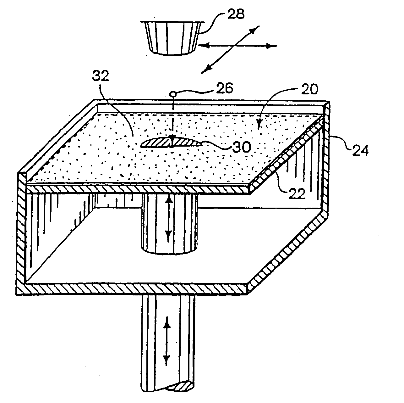
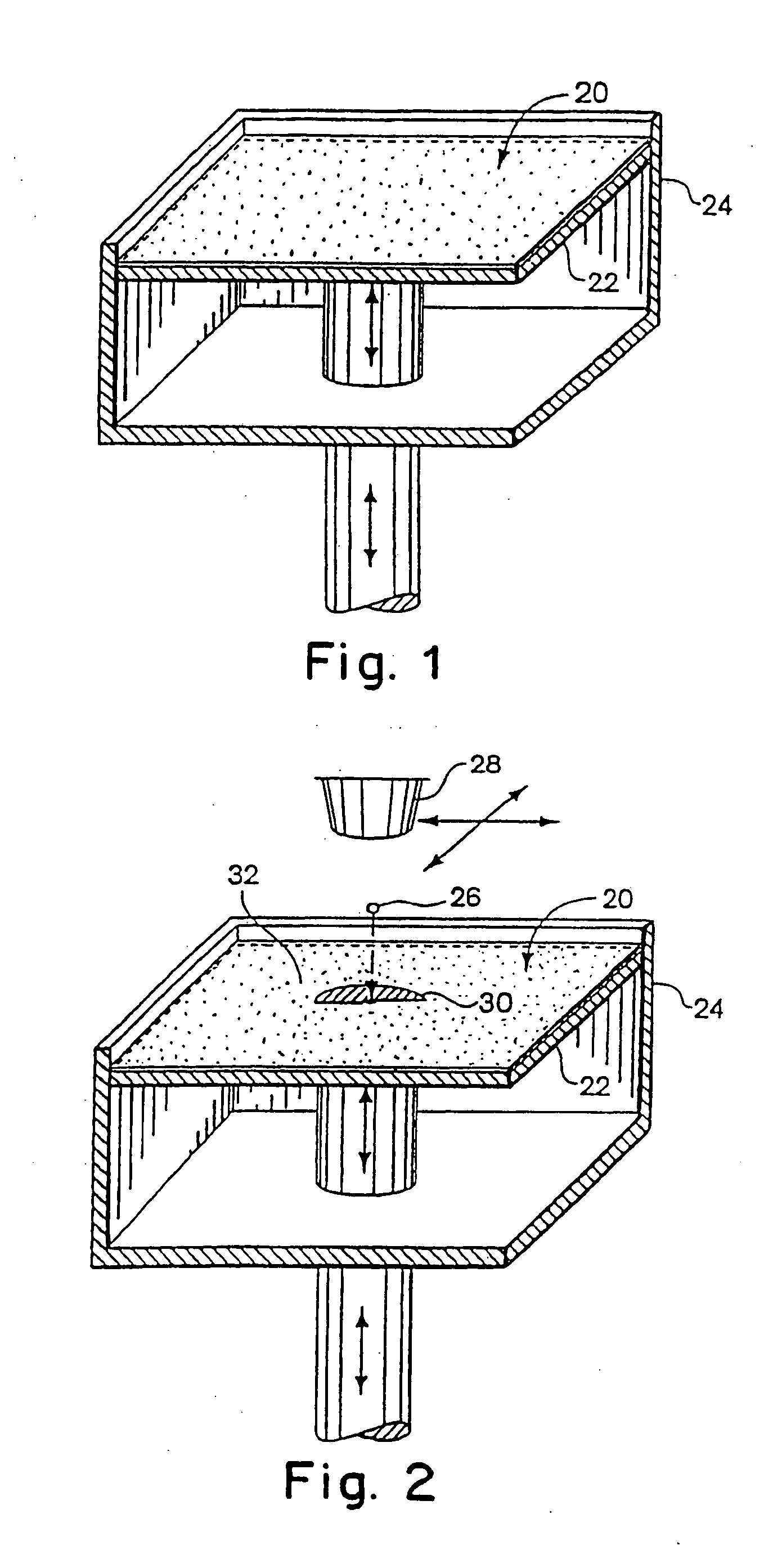
The present invention is directed to three-dimensional printing material systems and method, and an article made therefrom. The method of the present invention includes building cross-sectional portions of a three-dimensional article, and assembling the individual cross-sectional areas in a layer-wise fashion to form a final article. The individual cross-sectional areas are built by using an ink-jet printhead to deliver a fluid to a particulate material that includes particulate material.

Description

RELATED APPLICATION [0001] This non-provisional application claims the benefit under Title 35, U.S.C. § 119(e) of co-pending U.S. provisional application Ser. No. 60 / 164,000, filed Nov. 5, 1999, entitled “MATERIAL SYSTEMS AND METHODS OF THREE-DIMENSIONAL PRINTING” by James F. Bredt et al., incorporated herein by reference.FIELD OF THE INVENTION [0002] This invention relates generally to rapid prototyping techniques, and more particularly to three dimensional printing materials, methods, and articles made therefrom. BACKGROUND OF THE INVENTION [0003] The field of rapid prototyping involves the production of prototype articles and functional parts, as well as ceramic shell molds for metal casting, directly from computer-generated design data. [0004] Two well-known methods for rapid prototyping include a selective laser sintering process and a liquid binder three dimensional printing process, as exemplified by U.S. Pat. No. 5,204,055. The techniques are similar to the extent that they ...

Claims


Application Information

Patent Timeline
Patent Type & Authority Applications(United States)
IPC IPC(8): B29C67/24B29C67/00
CPCB29C67/0059B29C67/0081B29C64/112B29C64/165B33Y70/00B33Y70/10
Inventor BREDT, JAMES F.ANDERSON, TIMOTHY C.RUSSELL, DAVID B.CLARK, SARAH L.DICOLOGERO, MATTHEW
Owner 3D SYST INC
Learn More