
Toner, toner manufacturing method, developer, image forming apparatus, and process cartridge for the image forming apparatus

Active Publication Date: 2006-09-14
RICOH KK
View PDF6 Cites 121 Cited by
  • Summary
  • Abstract
  • Description
  • Claims
  • Application Information

AI Technical Summary

Benefits of technology

[0021] Another object of the present invention is to provide a toner manufacturing method which can produce a toner having such properties as mentioned above.
[0022] Another object of the present invention is to provide an image forming apparatus and a process cartridge by which high quality images can be stably produced while the energy consumed in the fixing process can be reduced.

Problems solved by technology

In contact heat fixing methods, because the surface of a heating member (such as the heating roller) directly contacts the toner image, a part of the toner is adhered to the heating member and then re-transferred to the following sheet of the recording material, resulting in occurrence of the offset problem.
However, in order to downsize the device and lower the operation costs, oilless fixing devices without a fixing oil applying system or fixing devices applying a small amount of oil have been typically used.
However, a toner binder resin having too low thermal properties (such as low-temperature fixability) has poor thermostable preservability and causes a toner blocking problem.
However, when a toner including a large amount of release agent is manufactured by a conventional pulverization method, a major portion of release agent tends to exist on the surface of the resultant toner and causes a toner filming problem and a blocking problem.
It is difficult to use polyester resins because the polyester is polymerized at a high temperature of about 200° C.
Therefore, the metal salt is incorporated in the resultant toner particles, but it is difficult to remove all of the incorporated metal salt in a washing process.
However, when a high-molecular-weight resin is dissolved in a solvent, the viscosity of the solution is so large that the solution has poor granulation ability.
In this case, the resultant toner has poor low-temperature fixability.
However, the method has a drawback in that the toner structure cannot be sufficiently controlled and thereby colorants and release agents tend to exist on the surface of the toner.
However, the low-temperature fixability of the toner is insufficient.
In addition, salting out fine particles on core particles takes a long time resulting in increase of the manufacturing cost.

Method used


Image

  • Toner, toner manufacturing method, developer, image forming apparatus, and process cartridge for the image forming apparatus
  • Toner, toner manufacturing method, developer, image forming apparatus, and process cartridge for the image forming apparatus

Examples


example 1

Preparation of Colorant / Wax Dispersion

[0234] In a reaction vessel equipped with a stirrer and a thermometer, 543.5 parts of the polyester (P-1), 181 parts of a carnauba wax, and 1450 parts of ethyl acetate are mixed and the mixture is heated to 80° C. while agitated. After being heated at 80° C. for 5 hours, the mixture is cooled to 30° C. over 1 hour. Then 500 parts of the master batch (1) and 100 parts of ethyl acetate are added to the vessel, and the mixture is agitated for 1 hour to prepare a raw material dispersion (1).

[0235] Then 1500 parts of the raw material dispersion (1) are subjected to a dispersion treatment using a bead mill (ULTRAVISCOMILL (trademark) from Aimex Co., Ltd.). The dispersing conditions are as follows. [0236] Liquid feeding speed: 1 kg / hour [0237] Peripheral speed of disc: 6 m / sec [0238] Dispersion media: zirconia beads with a diameter of 0.5 mm [0239] Filling factor of beads: 80% by volume [0240] Repeat number of dispersing operation: 3 times (3 passes...

example 2

Preparation of Colorant / Wax Dispersion

[0258] In a reaction vessel equipped with a stirrer and a thermometer, 543.5 parts of the polyester (P-1), 181 parts of a carnauba wax, and 1450 parts of ethyl acetate are mixed and the mixture is heated to 80° C. while agitated. After being heated at 80° C. for 5 hours, the mixture is cooled to 30° C. over 1 hour. Then 500 parts of the master batch (1) and 10 parts of ethyl acetate are added to the vessel, and the mixture is agitated for 1 hour to prepare a raw material dispersion (2).

[0259] Then 1500 parts of the raw material dispersion (2) are subjected to a dispersion treatment using a bead mill (ULTRAVISCOMILL (trademark) from Aimex Co., Ltd.). The dispersing conditions are as follows. [0260] Liquid feeding speed: 1 kg / hour [0261] Peripheral speed of disc: 6 m / sec [0262] Dispersion media: zirconia beads with a diameter of 0.5 mm [0263] Filling factor of beads: 80% by volume [0264] Repeat number of dispersing operation: 3 times (3 passes)...

example 3

Adherence of Particulate Resin

[0273] The dispersion (2) prepared in Example 2 and the dispersion of the particulate vinyl copolymer resin (V-1) prepared above are mixed at a mixing ratio of 1 / 0.2 based on a solid content. The mixture is heated to 73° C. taking 30 minutes.

[0274] A mixture liquid of 100 parts of ion-exchange water and 100 parts of magnesium chloride hexahydrate is gradually added thereto and kept for 5 hours at 73° C. Then pH of the mixture is controlled to be 5 by adding hydrochloric acid. The mixture is heated to 80° C. for 2 hours, and then cooled down. Thus, a dispersion (3-2) is prepared.

[0275] The procedure for preparation of the toner in Example 1 is repeated except the dispersion (1-2) is replaced with the dispersion (3-2). Thus, a toner (3) is prepared.


PUM


Abstract

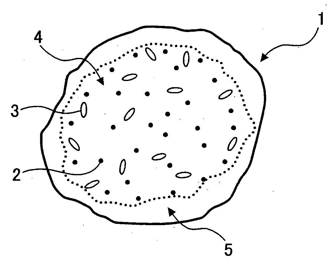
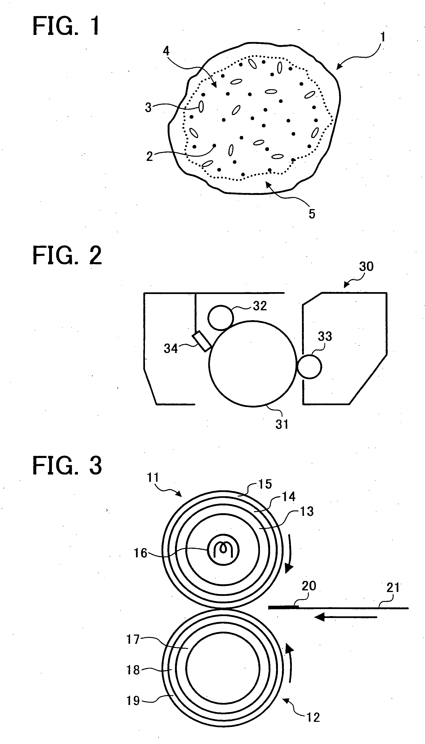
A toner having a core containing a colorant, a release agent and a binder resin (A), and a shell containing a binder resin (B), the shell overlying the core, wherein the binder resin (A) contains a resin having a polyester skeleton, the binder resin (B) contains a vinyl copolymer resin, and a weight ratio of the shell to the core is from 0.05 to 0.5, and wherein the toner has a volume average particle diameter of from 3 to 8 μm; a toner manufacturing method of such the toner can be used in an image forming apparatus and in a process cartridge.

Description

BACKGROUND OF THE INVENTION [0001] 1. Field of the Invention [0002] The present invention relates to a toner for use in an electrophotographic image forming apparatus. In addition, the present invention also relates to a toner manufacturing method; an image forming apparatus and a process cartridge using the toner. [0003] 2. Discussion of the Background [0004] When a toner image formed by an electrophotographic image forming method is fixed, contact heat fixing methods such as a heat roller fixing method are typically used. A fixing device used for the heat roller fixing methods includes a heating roller and a pressing roller. A toner image formed on a recording material is fixed by passing through a nip formed between the heating roller and the pressing roller. [0005] In contact heat fixing methods, because the surface of a heating member (such as the heating roller) directly contacts the toner image, a part of the toner is adhered to the heating member and then re-transferred to t...

Claims


Application Information

Patent Timeline
IPC IPC(8): G03G9/093
CPCG03G9/0804G03G9/0806G03G9/09321G03G9/09335G03G9/09342G03G9/09371G03G9/09378G03G9/09392
Inventor NOZAKI, TSUYOSHINOZAKI, CHIYOSHINAKAMURA, MINORUYAMAMOTO, ATSUSHIYASUNAGA, HIDEAKI
Owner RICOH KK
Learn More