
Compact multimode laser with rapid wavelength scanning

a multi-mode laser and wavelength scanning technology, applied in semiconductor lasers, laser details, optical resonator shape and construction, etc., can solve the problems of inability to achieve continuous sweeping of output wavelength, inability to achieve syntune lasers with significant manufacturing infrastructure, and inability to achieve new wavelength implementation. , to achieve the effect of sufficient coherence length and large scanning ra

Inactive Publication Date: 2006-09-14
THORLABS INC
View PDF31 Cites 81 Cited by
  • Summary
  • Abstract
  • Description
  • Claims
  • Application Information

AI Technical Summary

Benefits of technology

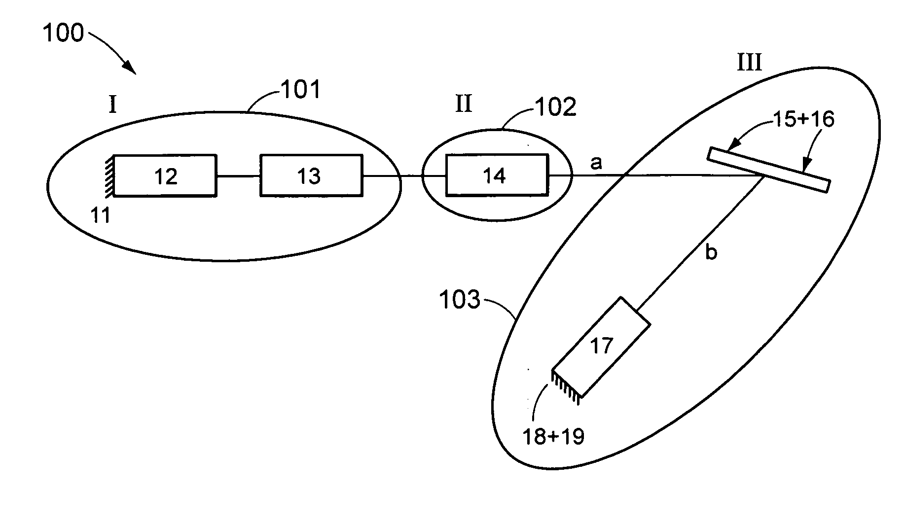
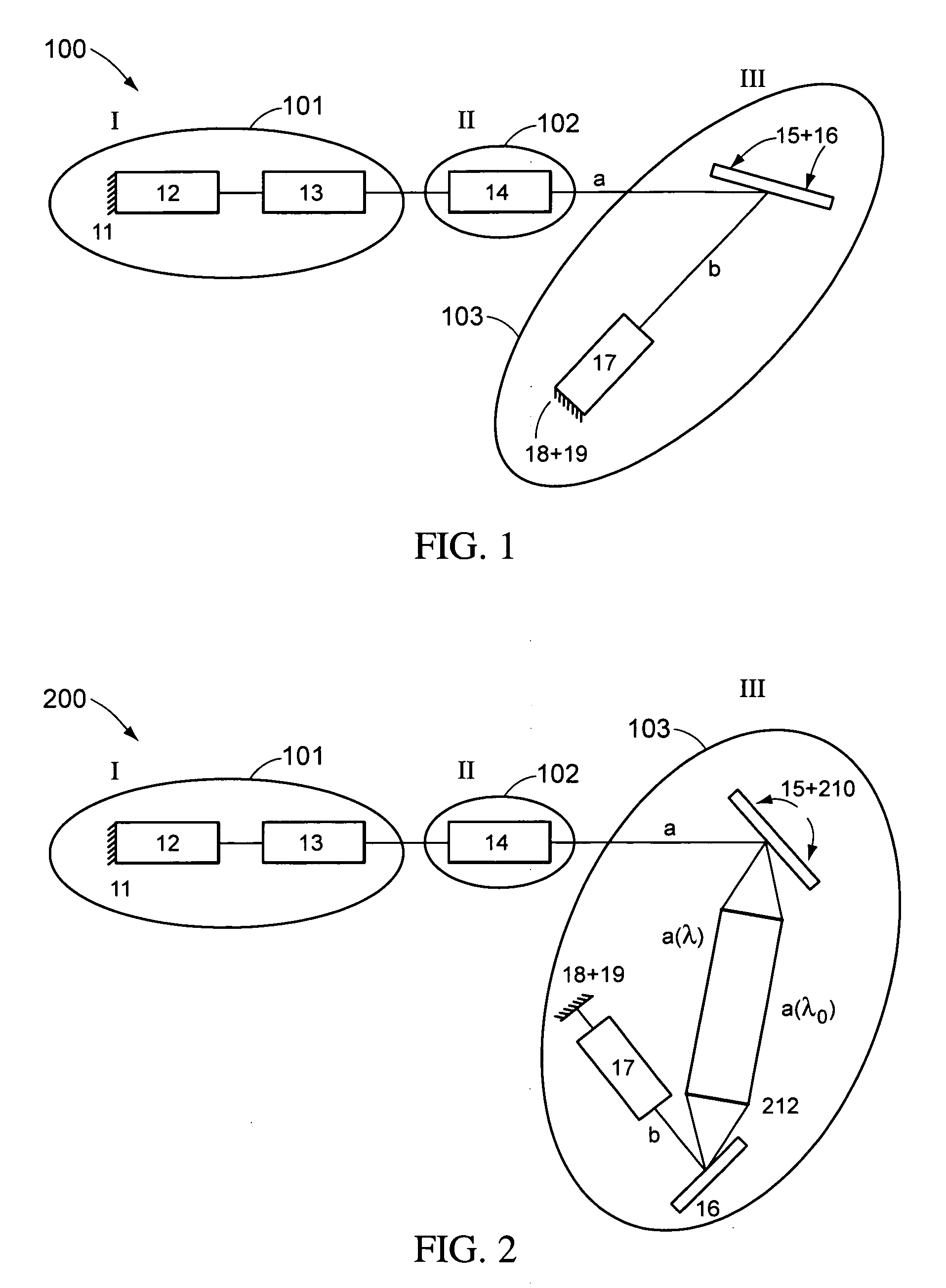
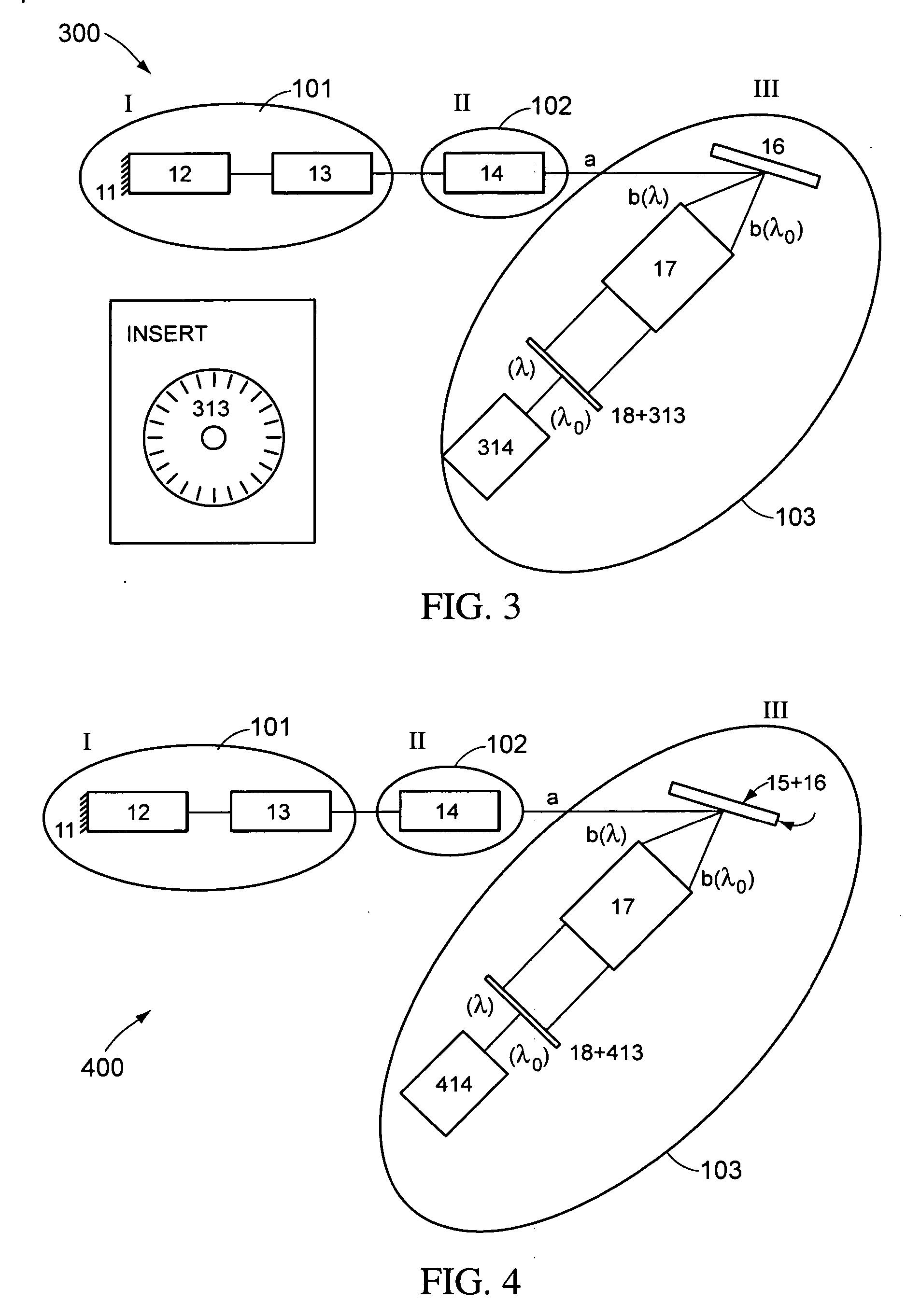
[0014] In accordance with the present invention, a nearly continuous wavelength scanning multimode laser is presented that has a large scanning rate while maintaining sufficient coherence length to be utilized in swept-source applications. In some embodiments of the present invention, a compact laser light source can have a wavelength scanning range of over about 140 nm with variable scan rates of up to about 10 nm/ps and a coherence length of between about 3 mm to about 30 mm.
[0015] Instead of trying to maintain a single longitudinal mode or nearly single longitudinal mode as the laser is scanned in wavelength, as is attempted in other systems as described above, some embodiments of the present invention provide a laser design that is intentionally multimode. Additionally the tuning mechanism according to some embodiments of the present invention is such that as the laser is tuned in wavelength the family of longitudinal cavity modes changes significantly, by sometimes many tens of thousands of modes.
[0016] A compact laser system according to some embodiments of the present invention includes an optical cavity, a light generating and optical gain medium section, and a beam shaping optical system; an optical propagation medium; and a fast mechanical wavelength tuning section positioned to receive light from the light generating section a

Problems solved by technology

More specifically, fast ECLs with tuning speeds greater than 1,000,000 nm / s, tuning ranges of at least 5% of the center wavelength, and coherence lengths of at least several millimeters are not currently available commercially.
Lack of wavelength tuning speed is a major disadvantage in present ECLs in that there are many applications that would benefit from substantially increased tuning speeds.
However, such systems do not offer continuous sweeping of their output wavelength.
Further, the Syntune laser requires a significant manufacturing infra-structure and is not easily implemented at new wavelengths.
The Micron Optics system, however, utilizes an intra-cavity fiber optic element and is susceptible to unwanted polarization variations as well as being limited to tuning speeds much less than that required by high-speed applications.
Additionally, the Micron Optics system is a fiber based laser and as such it is difficult to make the cavity sufficiently short to enable very high tuning rates.
While there are several mechanical solutions that may satisfy the requirements of the two equations shown above, those that are found commercially or in the scientific literature are limited, due to their size, to tuning speeds significantly below the desired tuning speeds.
The mechanics required to rotate a mirror or grating in accordance with the Equation 2 above with N fixed are almost always complicated mechanisms that have large inertial mass, which prevents them from being actuated at the high speeds required for rapid tuning.
Utilizing a resonant scanner provides a convenient means to achieve both these objectives; however this method typically has the rotation axis centered on the moving optical element, and Equation 2 cannot generally be met when N is held constant.
With these mode jumps present, the laser will no longer be a continuously tunable laser, and the dynamic coherence length of the laser will become erratic and degrade below the static coherence length of the system.
While this approach seems feasible, to our knowledge, there has been no successful implementation of this proposed design.

Method used


Image

  • Compact multimode laser with rapid wavelength scanning
  • Compact multimode laser with rapid wavelength scanning
  • Compact multimode laser with rapid wavelength scanning

Examples


Embodiment Construction

[0031] In accordance with some embodiments of the present invention, a tunable laser system that provides more than 5 mW of average optical power delivered from a single mode optical fiber, a dynamic coherence length of greater than about 2 mm, a tuning range (measured at the 99% power points) of approximately 5% of the center wavelength when operating at a center wavelength of, for example, about 850 nm, and approximately 10% of the center wavelength when operating at a center wavelength of, for example, about 1330 nm, and a tuning speed that is continuously variable from 0 to about 2,000,000 nm / s is presented. In some embodiments, additional discrete increases in tuning speed up to about 10,000,000 nm / s can also be obtained with the upper limit on the tuning speed being limited by the availability of appropriate high speed scanners or high speed tunable optical filters. In some embodiments, the polarization state of laser light emitted from the laser is linearly polarized and high...


PUM


Abstract

In accordance with the present invention, a compact laser system with nearly continuous wavelength scanning is presented. In some embodiments, the compact laser system can be scanned over a broad range. In some embodiments, the compact laser system can be scanned at high scan rates. In some embodiments, the compact laser system can have a variable coherence length. In particular, embodiments with wavelength scanning over 140 nm with continuously variable scan rates of up to about 1 nm / μs, and discrete increase in scan rates up to about 10 nm / μs, and variable coherence lengths of from 1 mm to about 30 mm can be achieved.

Description

RELATED APPLICATIONS [0001] The present application claims priority to U.S. Provisional Application No. 60 / 647,078, “Compact Laser with Continuous Wavelength Scanning,” by Alex Cable, Michael Larsson, Lars Sandstrom, and Bengt Kleman, filed on Jan. 24, 2005, which is herein incorporated by reference in its entirety.BACKGROUND [0002] 1. Field of the Invention [0003] The present invention is related to a tunable multimode laser and, in particular, to a compact laser with mode-hopping wavelength scanning. [0004] 2. Discussion of Related Art [0005] External Cavity Lasers (ECLs) are now commonly used in several applications where a continuously tunable laser source is needed. Although there are many commercial manufacturers of ECLs, covering a broad range of designs on the market, there are still many applications that would benefit from a dramatic increase in the tuning speed that current designs cannot offer, even if this increase comes at the expense of other operating parameters of t...

Claims


Application Information

Patent Timeline
IPC IPC(8): H01S3/10
CPCH01S3/08063H01S3/1055H01S5/024H01S5/146H01S5/028H01S5/141H01S5/143H01S5/02415
Inventor CABLE, ALEX EZRALARSSON, JOHAN MICHAELSANDSTROM, LARS GORANKLEMAN, BENGT
Owner THORLABS INC
Learn More