Light source unit, illuminator and projection display
a technology of light source and illuminator, which is applied in the direction of point-like light sources, lighting and heating devices, instruments, etc., can solve the problems of large size of light source apparatus, loss of much of light passing through the light-emitting portion again, and large outer shape of outer shap
- Summary
- Abstract
- Description
- Claims
- Application Information
AI Technical Summary
Benefits of technology
Problems solved by technology
Method used
Image
Examples
first embodiment
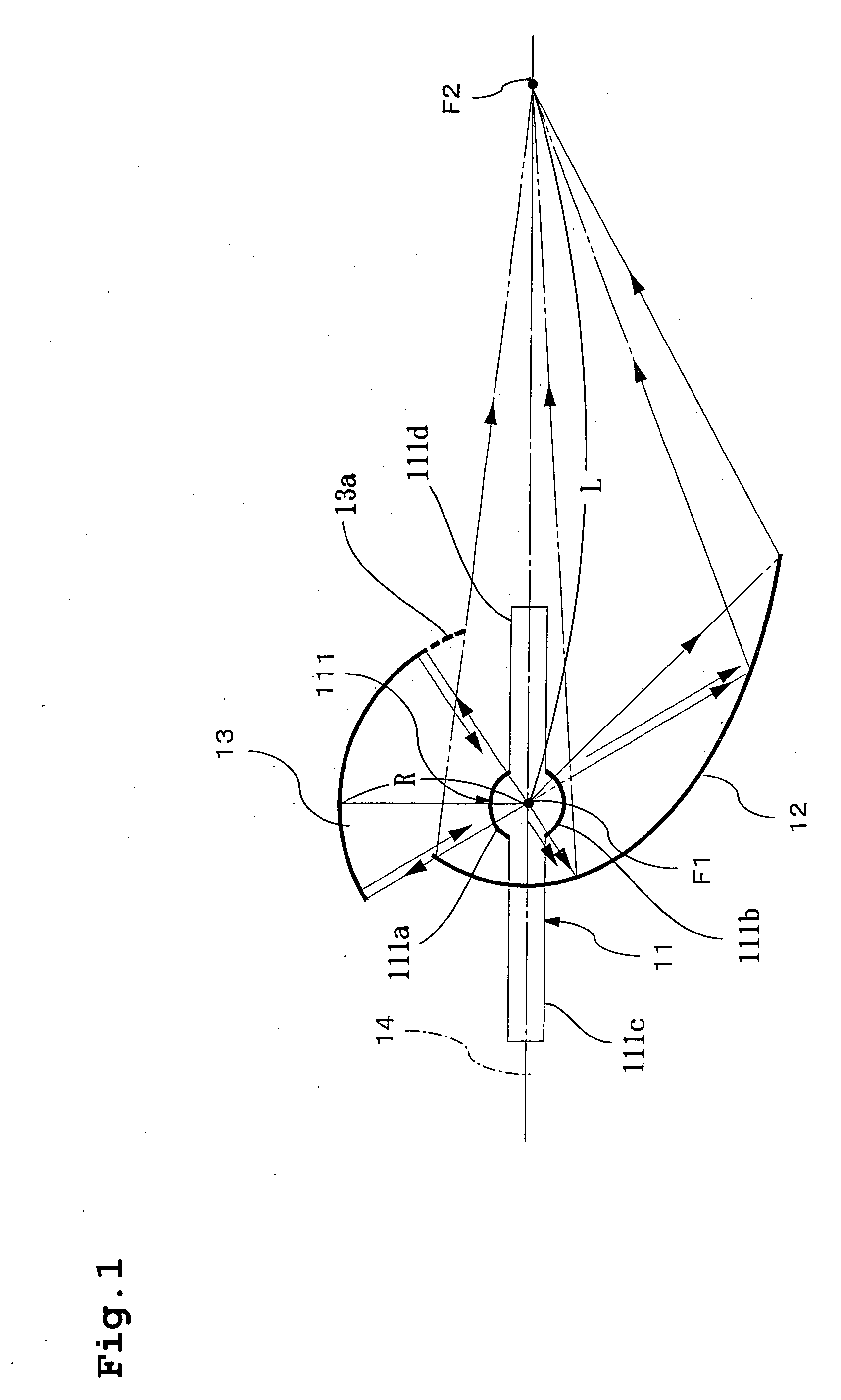
[0084] Hereunder, a first embodiment of the present invention will be described by referring to the drawings. FIG. 1 shows an overview configuration of a light source apparatus according to the first embodiment.
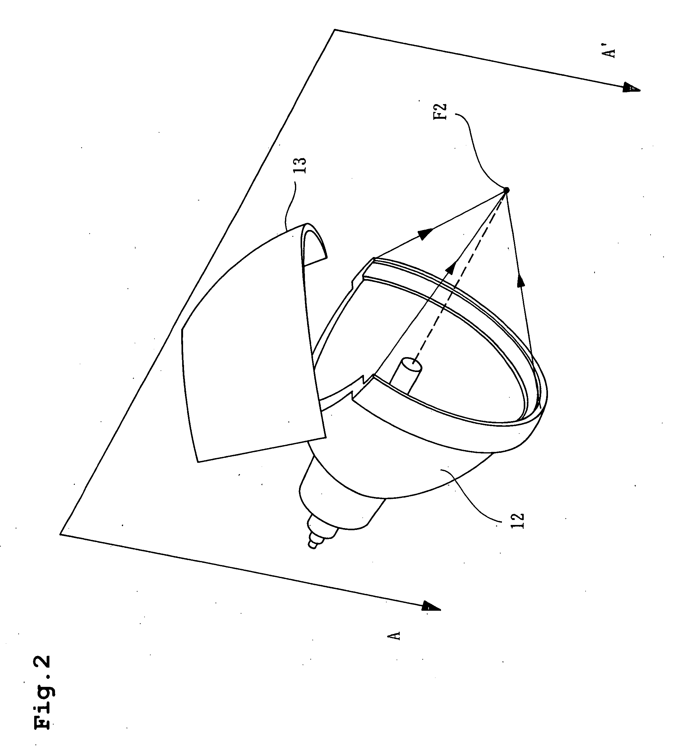
[0085] This light source apparatus is configured by a lamp (an example of the lamp or light generating means of the present invention) 11, an ellipsoidal mirror (an example of a first concave mirror of the present invention) 12 and a spherical mirror (an example of a second concave mirror of the present invention) 13.
[0086] The lamp 11 is configured by a lamp light-emitting portion 111 having a substantially spherical vessel portion including a source of luminescence positioned correspondingly to a focal position mentioned later and generating light, and light transmission planes 111a and 111b containing the source of luminescence and transmitting the light therefrom to the outside, and a pair of ends 111c and 111d including electrodes of the source of luminescence and havi...
second embodiment
[0122] Hereunder, a second embodiment of the present invention will be described by referring to the drawings. FIGS. 8 and 10 show overview configurations of the lighting apparatus and the projection display apparatus according to this embodiment.
[0123] The light source apparatus 100 is the same as that in the first embodiment, and so a description thereof will be omitted. As previously described, a multi-lamp optical system as shown in FIG. 11 uses multiple light source apparatuses to be able to perform brighter illumination, combines the luminous fluxes emitted from each of the multiple light source apparatuses and has them incident on one piece of rod integrator or lens optical system to perform the illumination.
[0124] In the case of the optical system using a rod integrator 2 shown in FIG. 11, it is necessary, for the sake of reducing the loss in the optical system from the rod integrator 2 onward and improving the optical usable efficiency of the luminous fluxes emitted from ...
third embodiment
[0149]FIG. 18 shows the configuration of the lighting apparatus according to a third embodiment of the present invention. In FIG. 18, the rod integrator 101, a relay lens 102 and the light modulation device 105 are the same as the conventional examples and the second embodiment. To be more specific, it has the configuration in which the light source apparatus according to the first embodiment is used as the light source apparatus of the lighting apparatus of the conventional example shown in FIG. 11. In this case, the pair of light source apparatuses 100 is placed to have their spherical mirrors 13 opposed to each other, and the rod integrator 101 is placed at an intersection which is a point in space at which the optical axes 14 of the light source apparatuses 100 intersect.
[0150] The lighting apparatus of this embodiment has the same optical operation as the conventional example of FIG. 11. It uses the light source apparatuses of the first embodiment as the pair of light source a...
PUM
 Abstract
Description
Claims
Application Information
 - R&D
- Intellectual Property
- Life Sciences
- Materials
- Tech Scout
- Unparalleled Data Quality
- Higher Quality Content
- 60% Fewer Hallucinations
Browse by: Latest US Patents, China's latest patents, Technical Efficacy Thesaurus, Application Domain, Technology Topic, Popular Technical Reports.
© 2025 PatSnap. All rights reserved.Legal|Privacy policy|Modern Slavery Act Transparency Statement|Sitemap|About US| Contact US: help@patsnap.com


