
Valve assembly with angled valve guide

a valve assembly and guide technology, applied in the direction of valve housings, liquid fuel engines, machines/engines, etc., can solve the problems of valves and seats normally failing, high abrasive particles present in fluids, and finite service life, so as to increase the service life of the valve assembly and reduce the friction between components

Inactive Publication Date: 2006-09-14
NAT OILWELL DHT
View PDF8 Cites 17 Cited by
  • Summary
  • Abstract
  • Description
  • Claims
  • Application Information

AI Technical Summary

Benefits of technology

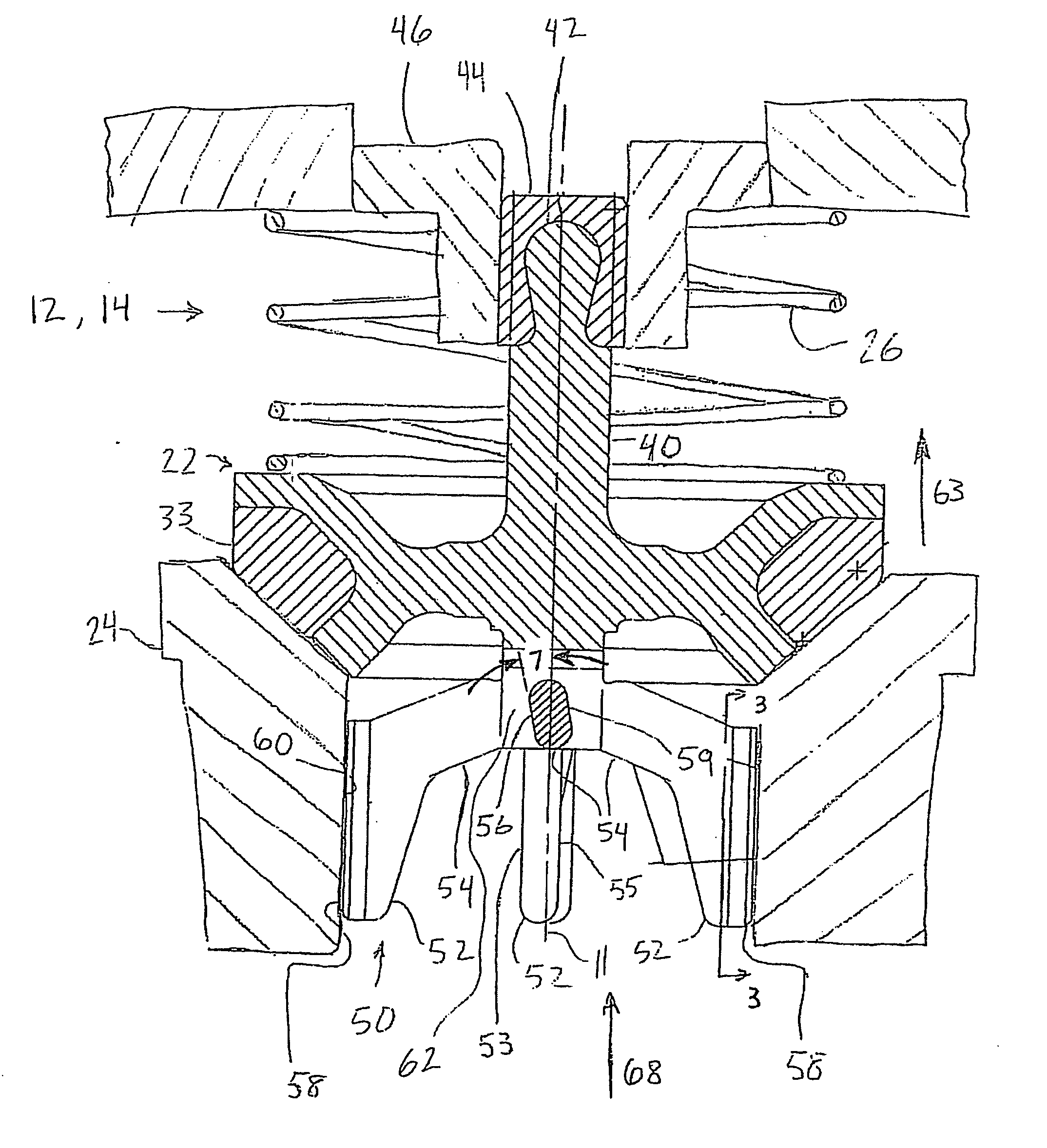
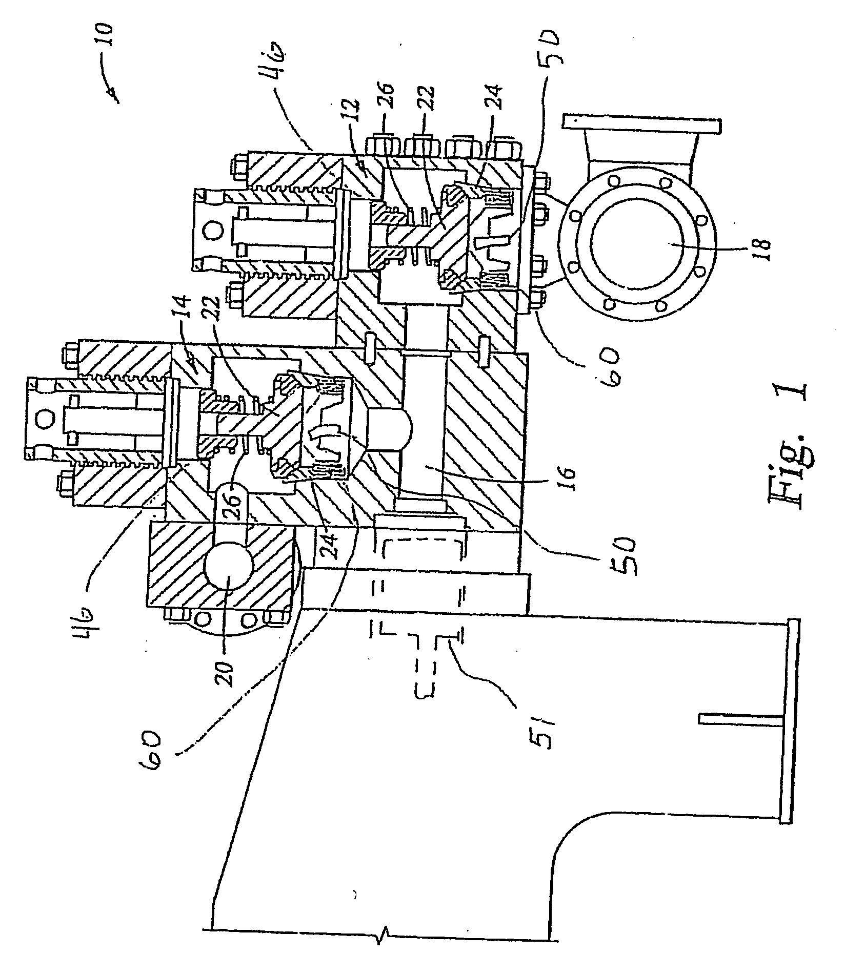
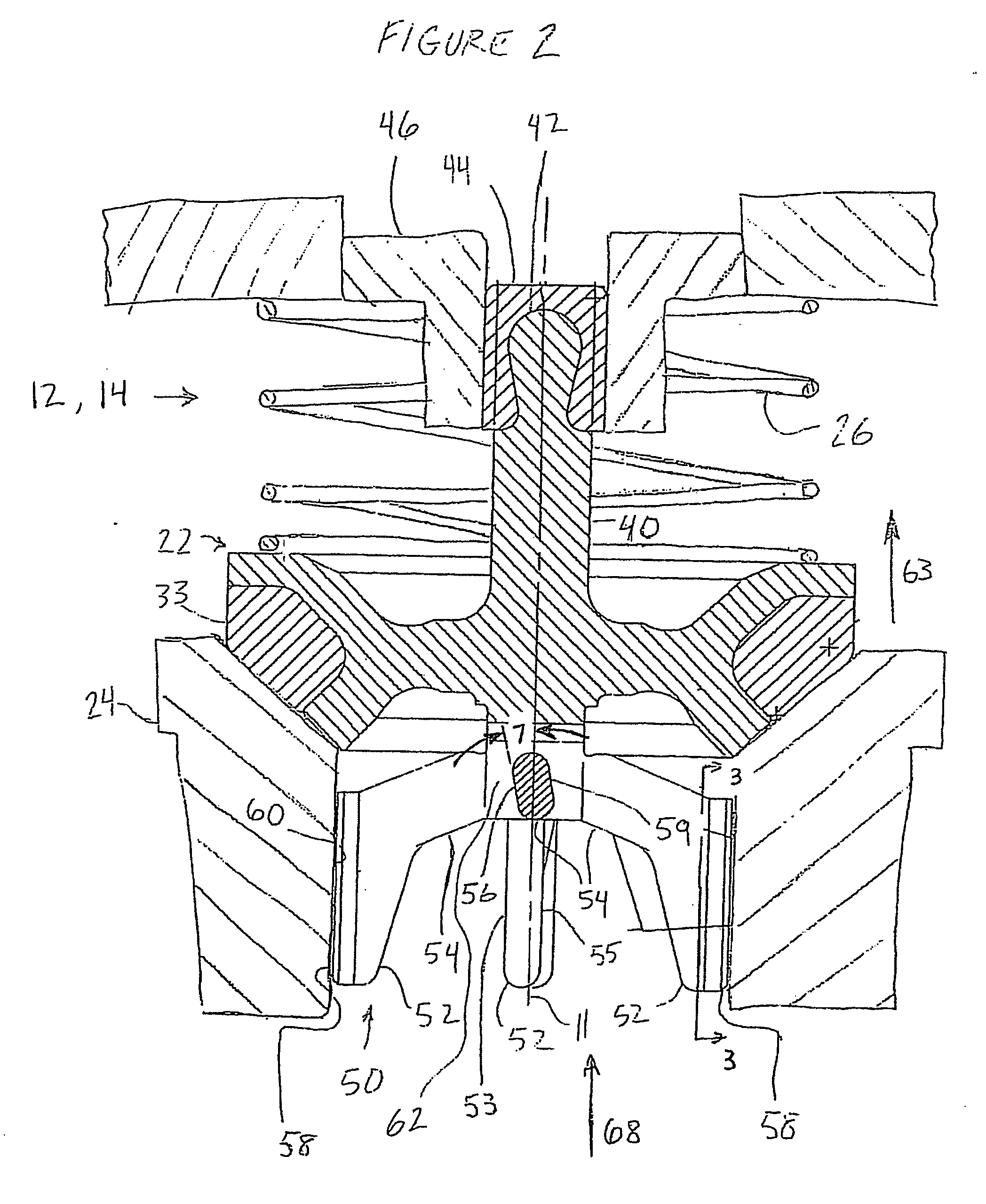
[0007] The embodiments described herein are directed toward methods and apparatus for increasing the service life of a valve assembly. More specifically, the described embodiments comprise valve guides with canted or angled lateral support members which allow fluid flow to impart a rotational force on the valve member (i.e., the closure member) of the valve assembly. Consequently, the valve member strikes a seating member in different rotational positions during repetitive cycling of the valve assembly. Certain embodiments also comprise an elastomeric upper stem guide that compensates for misalignment and reduces friction between components.

Problems solved by technology

Nevertheless, highly abrasive particles are present in the fluids that are being pumped through the system.
Due to the abrasive and corrosive nature of most drilling fluids, these valves have a finite service life and must be replaced when the leakage rate increases to a point that the pump will not maintain satisfactory pressure for the drilling conditions.
These valves and seats normally fail due to a deterioration of the elastomer sealing element of the valve, erosion cause by fluid cutting of the valve and seat metal contact surfaces, or a combination of these two.

Method used


Image

  • Valve assembly with angled valve guide
  • Valve assembly with angled valve guide
  • Valve assembly with angled valve guide

Examples


Embodiment Construction

[0007] The embodiments described herein are directed toward methods and apparatus for increasing the service life of a valve assembly. More specifically, the described embodiments comprise valve guides with canted or angled lateral support members which allow fluid flow to impart a rotational force on the valve member (i.e., the closure member) of the valve assembly. Consequently, the valve member strikes a seating member in different rotational positions during repetitive cycling of the valve assembly. Certain embodiments also comprise an elastomeric upper stem guide that compensates for misalignment and reduces friction between components.

[0008] The various characteristics described above, as well as other features, will be readily apparent to those skilled in the art upon reading the following detailed description of the preferred embodiments of the invention, and by referring to the accompanying drawings.

BRIEF DESCRIPTION OF THE DRAWINGS

[0009] For a more detailed description ...


PUM


Abstract

A valve assembly is disclosed comprising a valve member with an elastomeric upper stem guide and a lower valve guide comprising lateral support members including an angled surface. During operation, fluid impacting the angled surface imparts a rotational force on the lower valve guide and valve member. Consequently, the valve member strikes a sealing member in different rotational positions during repetitive cycling of the valve assembly.

Description

CROSS-REFERENCE TO RELATED APPLICATIONS [0001] The present application claims priority to U.S. Provisional Application No. 60 / 661,581, filed Mar. 14, 2005, and titled “Leg Guide Valve Assembly,” which is hereby incorporated by reference herein for all purposes.STATEMENT REGARDING FEDERALLY SPONSORED RESEARCH OR DEVELOPMENT [0002] Not Applicable. BACKGROUND INFORMATION [0003] The present invention relates generally to methods and apparatus for controlling flow in a pump. More particularly, the present invention relates to suction and discharge valves for reciprocating pumps used to pump fluids. [0004] Suction and discharge valves are used in reciprocating pumps to control the flow of fluid into and out of the cylinders in which the fluid is pressurized. Reciprocating pumps are used in various operations to pressurize an often abrasive slurry mixture of solids and liquids. For example, reciprocating pumps are used in drilling operations to pressurize a slurry mixture of solids and liq...

Claims


Application Information

Patent Timeline
IPC IPC(8): F16K27/02
CPCF04B53/1027F16K15/063F16K47/06F16K47/12F16K29/00
Inventor JOHNSON, JERRY E.
Owner NAT OILWELL DHT
Learn More