
Link belt assembly and method for producing same

a technology of interlocking links and conveyor belts, which is applied in the direction of driving chains, mechanical equipment, transportation and packaging, etc., can solve the problems of accelerating wear of various components of the conveyor assembly, unfavorable noise and/or vibration, and degrading the work place environment, so as to achieve the effect of reconnection and convenient separation

Inactive Publication Date: 2006-09-14
FENNER PLC
View PDF42 Cites 3 Cited by
  • Summary
  • Abstract
  • Description
  • Claims
  • Application Information

AI Technical Summary

Benefits of technology

[0006] According to another aspect, a link belt having elements attached to the top surface is provided wherein the link belt can be readily separated and reconnected along the length of the belt.

Problems solved by technology

The interface between the machine element and the surface transitions on the belt leads to undesirable noise and / or vibrations.
The vibrations can lead to accelerated wear of various components of the conveyor assembly.
In addition, the significant noise produced degrades the work place environment and introduces dangers associated with high-noise environments.

Method used


Image

  • Link belt assembly and method for producing same
  • Link belt assembly and method for producing same
  • Link belt assembly and method for producing same

Examples


Embodiment Construction

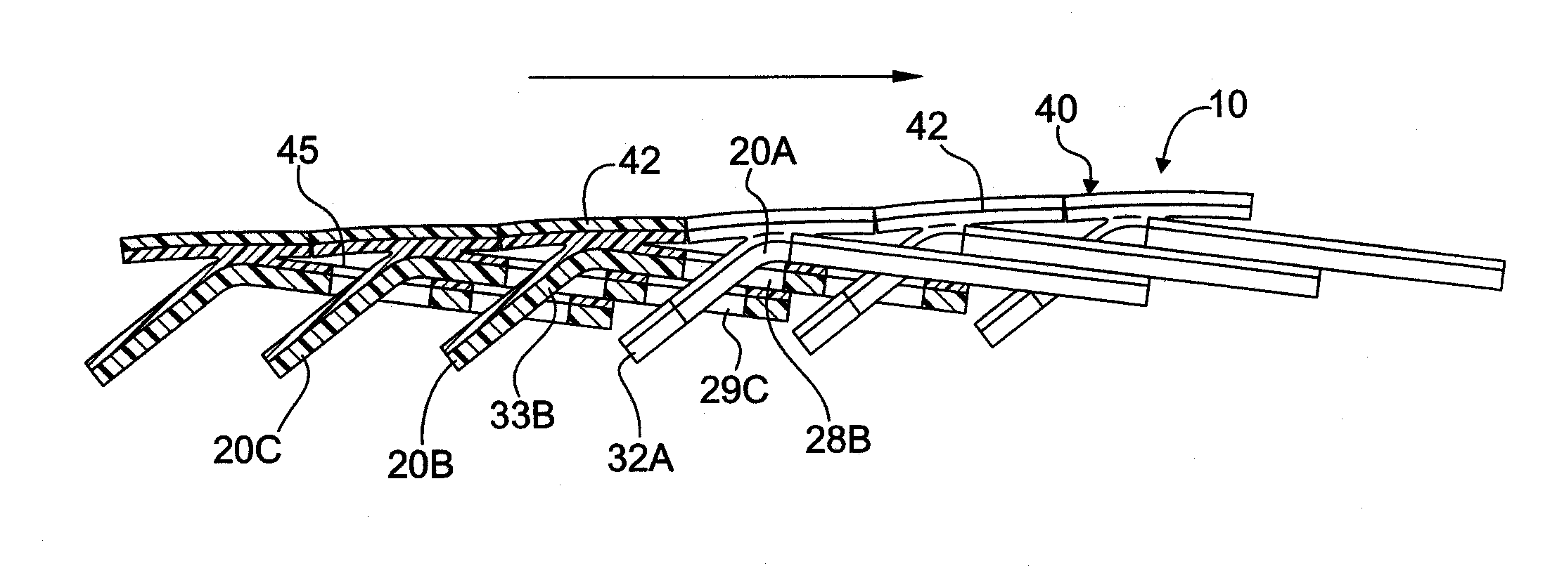
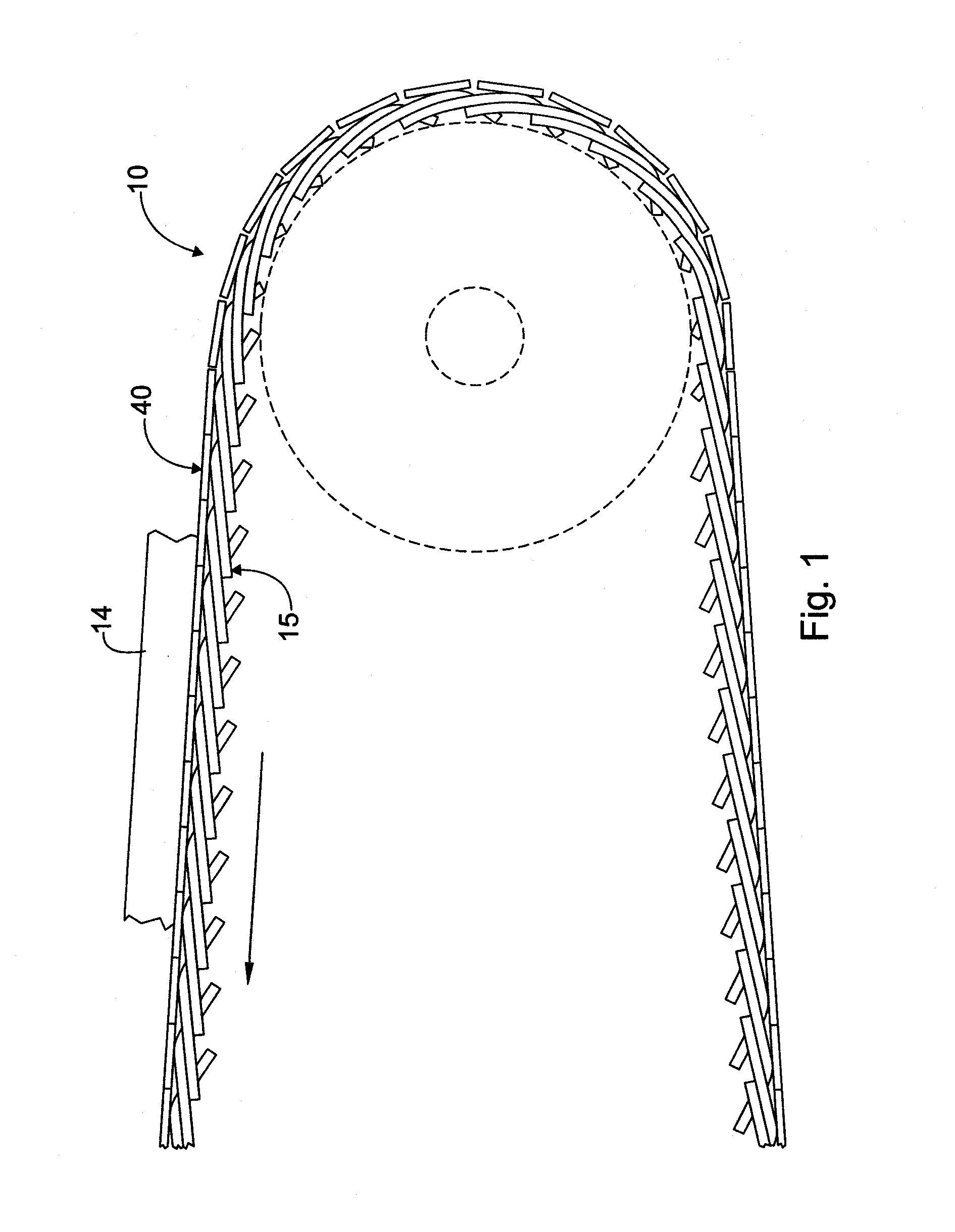
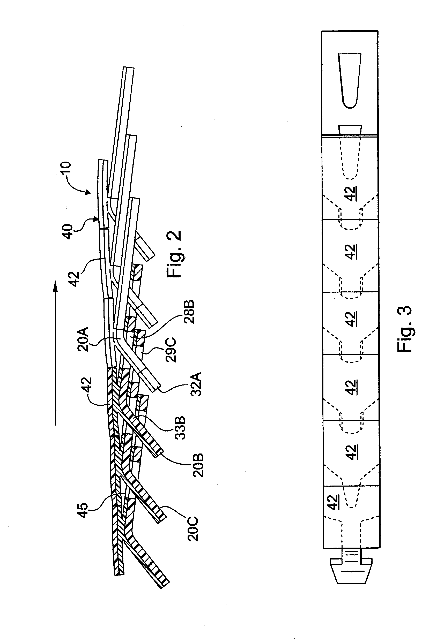
[0004] Accordingly, the present invention provides a link belt configured to overcome one or more of the shortcomings of the known belts so that the belt can be used in a variety of applications. For instance, according to one aspect, a link belt having a generally smooth upper surface is provided.

[0005] According to one embodiment, the smooth surface may be provided by attaching one or more elements to the top surface of the belt after the belt links are connected together to form a length of belt. More specifically, a length of a generally flat material may be attached to the top surface of the link belt so that the flat material forms the upper surface of the belt.

[0006] According to another aspect, a link belt having elements attached to the top surface is provided wherein the link belt can be readily separated and reconnected along the length of the belt.

[0007] In accordance with one embodiment, the elements attached to the top surface of the link belt may be configured and ...


PUM

PropertyMeasurementUnit
thickaaaaaaaaaa
thicknessaaaaaaaaaa
transmitting poweraaaaaaaaaa

Abstract

A belt for power transmission and for conveying elements is provided wherein the belt comprises a top layer attached to the top surface of the belt. The top layer provides a generally smooth top surface for the belt. The belt preferably is a link belt and the top surface of the belt comprises a bonding layer for adhering the top layer to the belt. The bonding layer may be a thermoplastic urethane that is heat fusible with the compressible layer to adhere the compressible layer to the belt. A method is also provide in which a top layer is adhered to a link belt and the top layer is then severed into a plurality of separate elements.

Description

RELATED APPLICATIONS [0001] The present application is a continuation-in-part of co-pending U.S. patent application Ser. No. 10 / 978,682, filed Nov. 1, 2004, which is a continuation-in-part of U.S. patent application Ser. No. 10 / 767,954, filed Jan. 29, 2004, which claims priority to U.S. Provisional Patent Application No. 60 / 443,891, filed Jan. 31, 2003. The present application also claims priority to U.S. Provisional Patent Application No. 60 / 664,811, filed Mar. 24, 2005. Each of the foregoing applications is hereby incorporated herein by reference.FIELD OF THE INVENTION [0002] The present invention relates to interlocking-link conveyor belts and has particular use in applications in which it is desirable to have a flat surface to convey products. The present invention also relates to applications in which the top surface of an interlocking-link belt is used for power transmission. BACKGROUND OF THE INVENTION AND DISCUSSION OF PRIOR ART [0003] Link belts are generally known and used...

Claims


Application Information

Patent Timeline
Patent Type & Authority Applications(United States)
IPC IPC(8): B65G17/06
CPCB65G17/06B65G17/38Y10T156/1079F16G13/07B65G2201/02Y10T83/04
Inventor FATATO, FRANCIS B.BIGLER, JEREMY M.
Owner FENNER PLC
Learn More