Eureka AIR delivers breakthrough ideas for toughest innovation challenges, trusted by R&D personnel around the world.

Hydraulic hose with integral life-sensing capability and method therefor

a technology of life-sensing capability and hydraulic hose, applied in the field of valves, can solve the problems of a matter of seconds, hours or even minutes, and achieve the effect of accurate prediction of wall failur

Active Publication Date: 2006-09-07
PURDUE RES FOUND INC
View PDF18 Cites 99 Cited by
  • Summary
  • Abstract
  • Description
  • Claims
  • Application Information

AI Technical Summary

Benefits of technology

The present invention provides a system and method for predicting structural failure of a wall of a fluid containment vessel, such as a hydraulic hose or other type of pressurized conduit. The invention is adapted to provide an indication of localized yielding anywhere in the vessel wall, from which a warning of a catastrophic failure of the wall can be provided minutes if not hours before failure occurs. The system includes strain-sensing means between the innermost and outermost layers of the wall and means for sensing changes in an electrical property associated with the strain-sensing means resulting from distortion of the wall of the vessel. The method of this invention involves forming the wall to contain the strain-sensing means and sensing changes in the electrical property resulting from distortion of the wall of the vessel. The invention has been shown to enable accurate predictions of wall failure as a result of electrical changes being generally nominal until an abrupt electrical change occurs that sufficiently precedes failure to enable repair of the wall or replacement of the vessel before any harm occurs to the system or apparatus in which the vessel is used.

Problems solved by technology

However, in high pressure fluid components such as hydraulic hoses, once seepage occurs catastrophic failure is likely to occur in a matter of seconds, not hours or even minutes.

Method used


Image

  • Hydraulic hose with integral life-sensing capability and method therefor
  • Hydraulic hose with integral life-sensing capability and method therefor
  • Hydraulic hose with integral life-sensing capability and method therefor

Examples


first embodiment

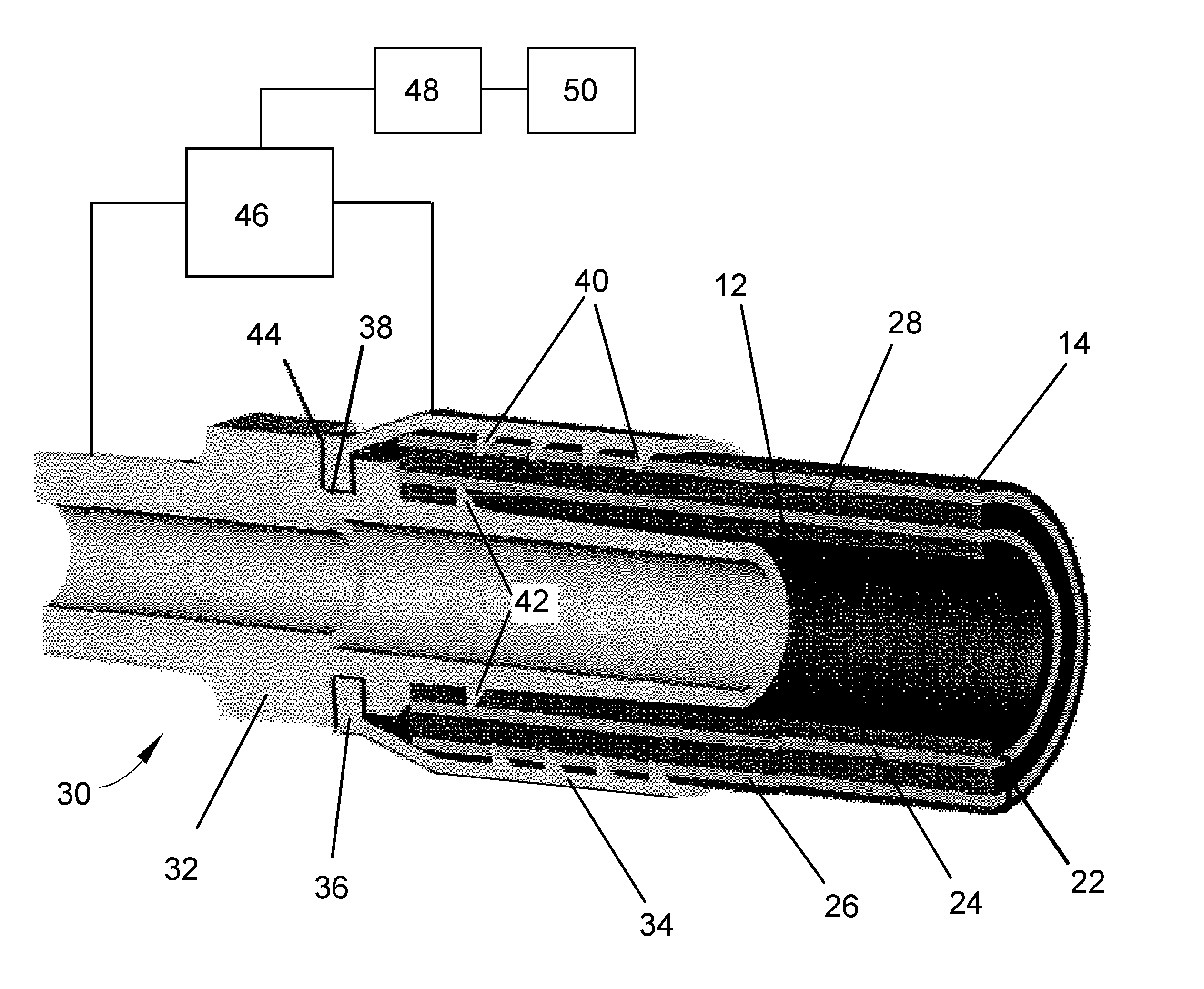
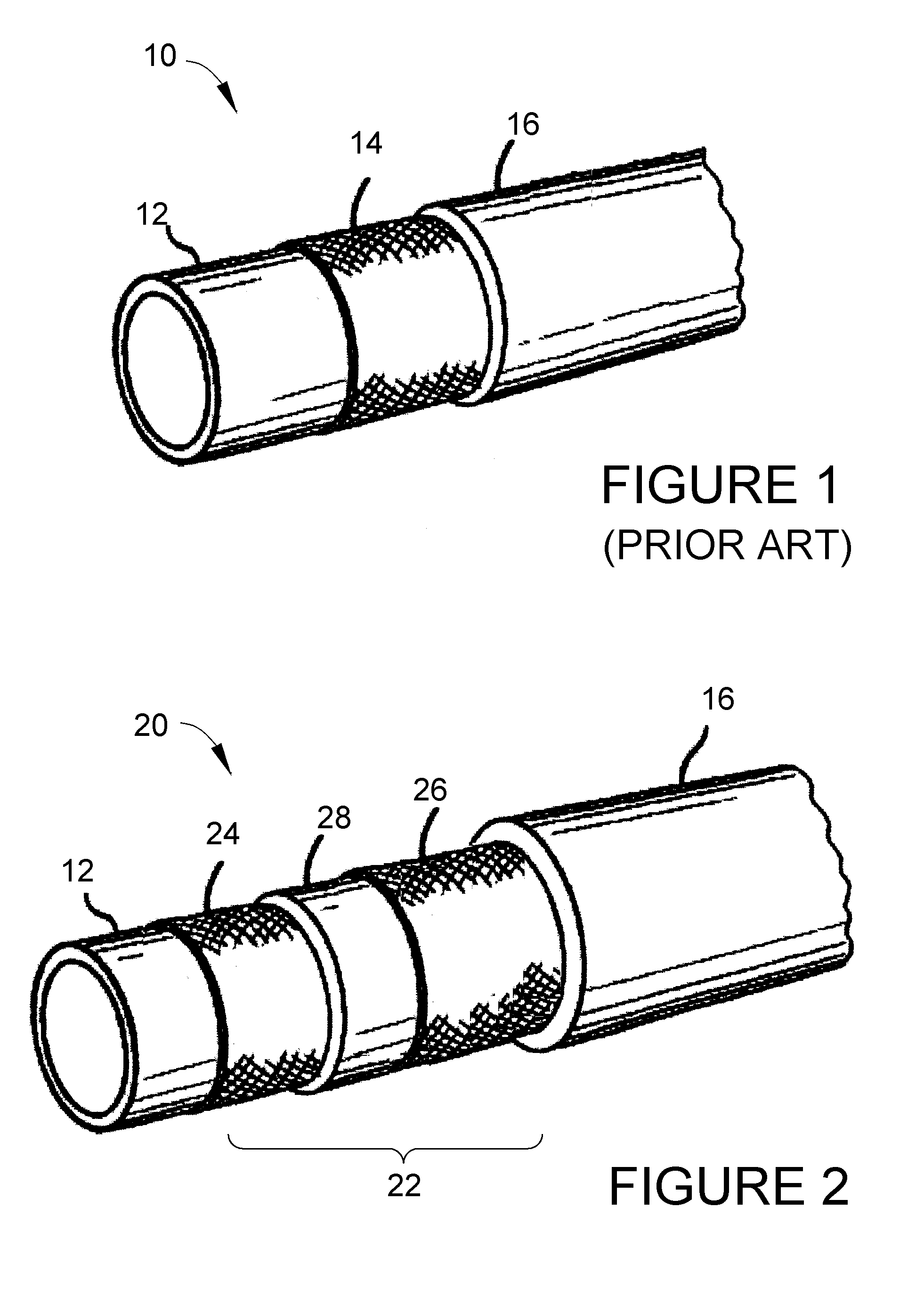
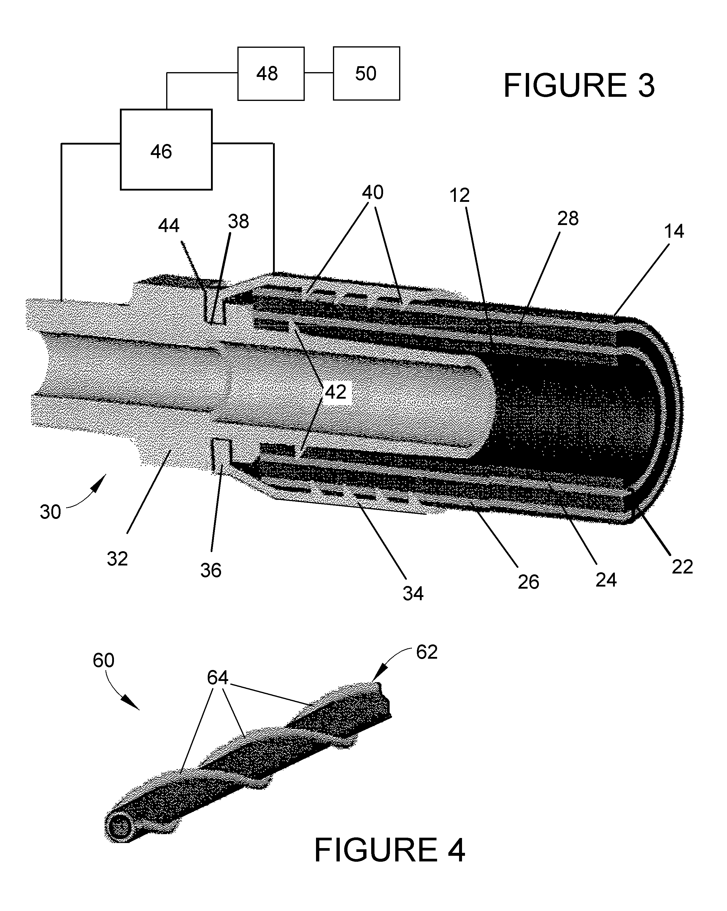
[0021]FIGS. 2 and 3 represent a hydraulic hose 20 according to the invention. Similar to the hose 10 of FIG. 1, the hose 20 has an inner tube 12 and an outer cover 16. Both of these components of the hose 20 are formed of electrically insulating materials, such as those materials noted above for the hose 10 in FIG. 1. However, in place of the reinforcement layer 14 of FIG. 1, the hydraulic hose 20 contains a multilayer strain-sensing structure 22 between the inner tube 12 and outer cover 16. In the embodiment of FIGS. 2 and 3, the strain-sensing structure 22 operates on the basis of electrical capacitance. The strain-sensing structure 22 is shown as comprising an inner conductive layer 24 surrounding the inner tube 12, an electrical insulating layer 28 surrounding the inner conductive layer 24, and an outer conductive layer 26 surrounding the insulating layer 28 and separated from the inner conductive layer 24 by the insulating layer 28 to define a capacitive couple comprising the i...

second embodiment

[0029]FIG. 4 represents the interior structure of a hydraulic hose 60 according to the invention. Similar to the hoses 10 and 20 of FIGS. 1 and 2, the hose 60 has an inner tube 12 that can be protected by an outer cover (not shown). Furthermore, the hose 60 may include a reinforcement layer (not shown) between the inner tube 12 and the outer cover. Suitable materials for these layers include those noted above for the corresponding layers of the hoses 10 and 20. However, in place of the conductive layers 24 and 26 and insulating layer 28 that make up the multilayer strain-sensing structure 22 of FIG. 2, the hose 60 of this embodiment has a strain-sensing structure 62 that may comprise one or more conductors 64 that surround the inner tube 12 to form one or more electrically isolated helical conductive paths along the length of the hose 60. According to this embodiment of the invention, the strain-sensing structure 62 operates on the basis of electrical resistance, and an impending fa...


PUM


Abstract

A system and method for predicting structural failure of a wall of a fluid containment vessel, such as a hydraulic hose or other type of pressurized conduit of types used in mobile machinery, automotive, aerospace, manufacturing, and process equipment. The wall of the vessel has an innermost layer for contact with the fluid contained by the vessel, and an outermost layer parallel with the innermost layer. The system includes strain-sensing means between the innermost and outermost layers and comprising at least one conductor parallel to the innermost layer of the wall. The system and method entail sensing changes in an electrical property associated with the at least one conductor resulting from distortion of the wall of the vessel causing distortion of the at least one conductor.

Description

CROSS REFERENCE TO RELATED APPLICATIONS [0001] This application claims the benefit of U.S. Provisional Application No. 60 / 658,932, filed Mar. 4, 2005, the contents of which are incorporated herein by reference.BACKGROUND OF THE INVENTION [0002] The present invention generally relates to vessels that contain static or flowing fluids, including conduits such as hydraulic hoses of the types used in mobile machinery, automotive, aerospace, manufacturing, and process equipment. More particularly, this invention relates to hydraulic hoses equipped with means for sensing the life of the hose in terms of wear, fatigue, and / or other structural breakdown of its components, and means for electrically monitoring the hose to predict a structural failure. [0003] Interest exists in developing methods for consistently predicting the failure of vessels containing fluids, including but not limited to hoses, thereby enabling replacement or repair of the vessel before failure. For example, U.S. Pat. No...

Claims


Application Information

Patent Timeline
Patent Type & Authority Applications(United States)
IPC IPC(8): F16L55/00
CPCF16L11/127F16L25/01F16L2201/30G01M3/18G01N27/24F16L33/2073
Inventor DECKARD, AARON DON
Owner PURDUE RES FOUND INC
Why Eureka
Eureka Blog
Learn More