
Device for graphically showing a schedule

Inactive Publication Date: 2006-09-07
BERTO JOSEPH
View PDF13 Cites 31 Cited by
  • Summary
  • Abstract
  • Description
  • Claims
  • Application Information

AI Technical Summary

Benefits of technology

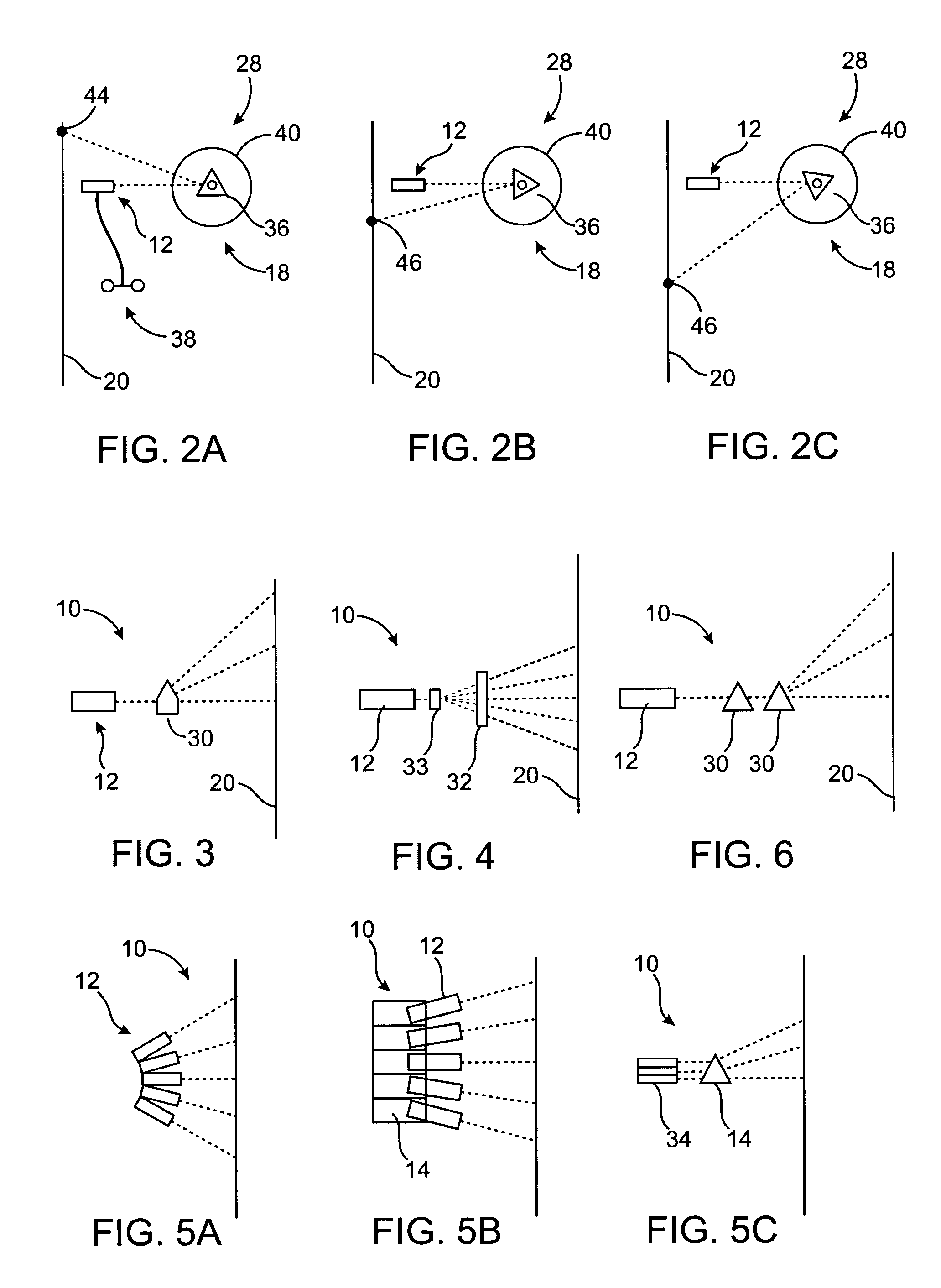
[0007] In accordance with another embodiment, a device that graphically shows a schedule comprising: at least one light source adapted to emit an intermittent visible beam of light; an electronic assembly adapted to control the intermittent timing of the emission of the beam of light by the light source; and a motor assembly adapted to rotate the light source through a plurality of positions, and project the intermittent beam of light onto a surface in the form of individual points of illumination corresponding to a schedule.
[0008] In accordance with a further embodiment, a device that graphically shows a schedule comprising: at least one light source adapted to emit an intermittent visible beam of light; a mirror configured to receive the beam of light; a motor assembly adapted to rotate the mirror assembly through a plurality of positions; an electronic assembly adapted to control the intermittent timing of the emission of the beam of light by the light source; and wherein the mirror receives the beam of light and projects the beam of light onto a surface in the form of individual points of illumination or segments corresponding to a schedule.
[0009] In accordance with another embodiment, a device that graphically shows a schedule comprising: at least one light source adapted to emit a visible beam of light; a laser line generator adapted to convert the beam

Problems solved by technology

However, none of these devices are configurable to display multiple or intermittent illuminated points or a segmented line.

Method used


Image

  • Device for graphically showing a schedule
  • Device for graphically showing a schedule
  • Device for graphically showing a schedule

Examples


Embodiment Construction

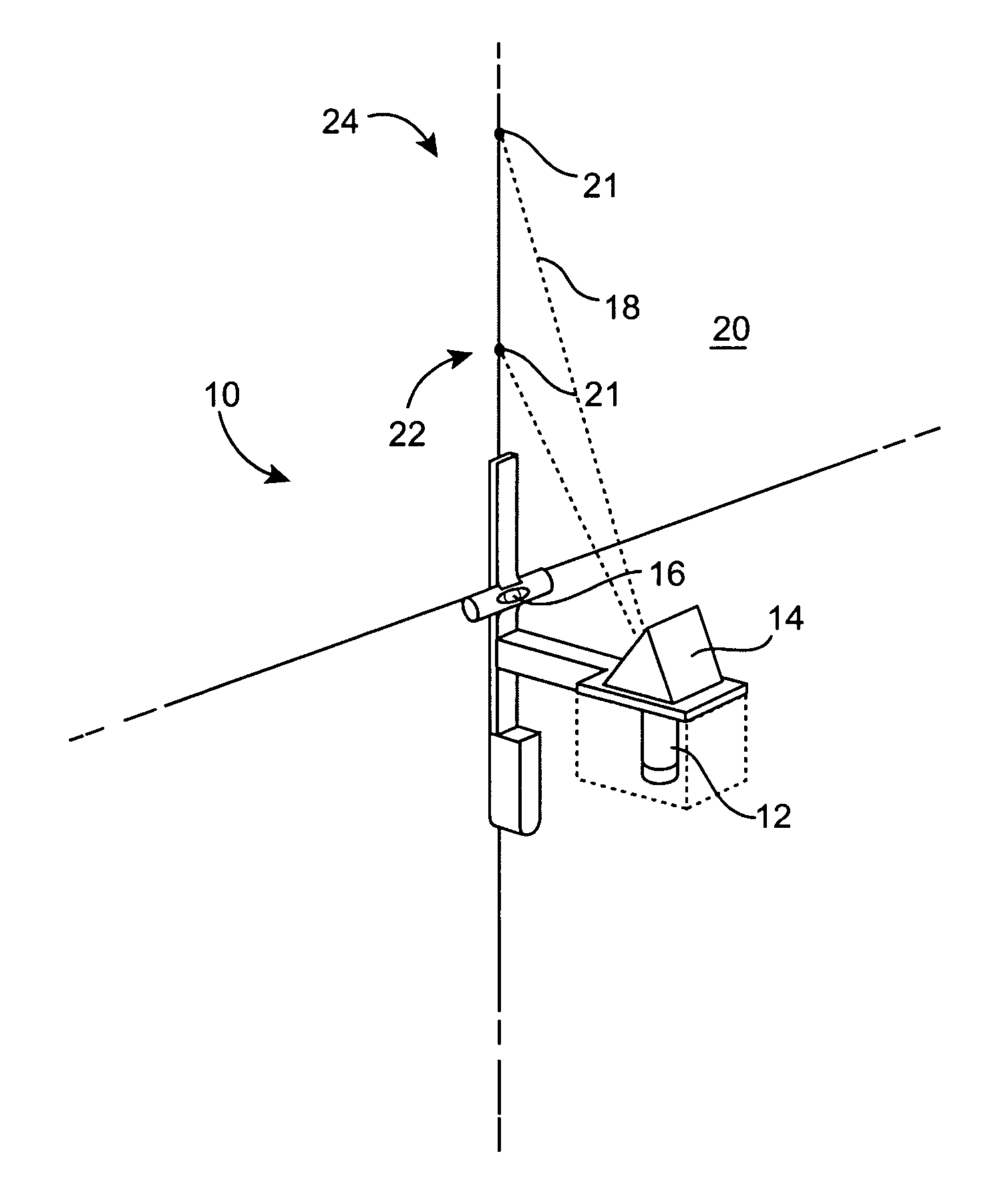
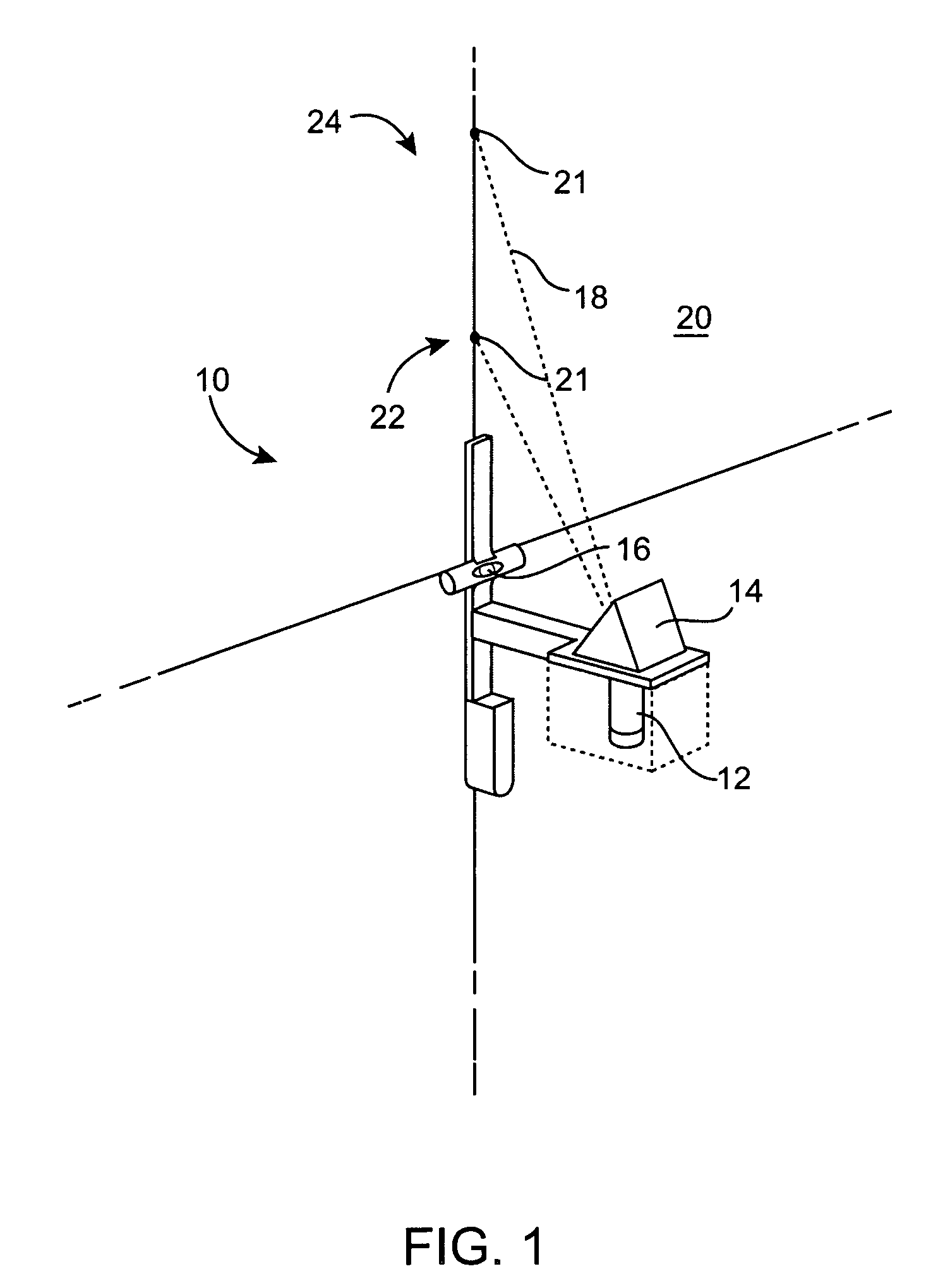
[0031]FIG. 1 shows a perspective view of a device 10 for graphically showing a spacing of individual points of light (schedule) 24. The device 10 can be used for laying out fastener spacing when mounting wallboard such as drywall, nailing decking to show spacing between studs or joists, laying out tile, or any application where a schedule 24 is desired.

[0032] As shown in FIG. 1, the device 10 comprises a light source 12 and an aiming device 14. In operation, the light source 12 is adapted to emit a visible or coherent beam of light 18, which the aiming device 14 receives and projects the beam of light 18 onto a surface 20. For example as shown in FIG. 1, the surface 20 can be a sheet of wallboard, wherein the projection device 10 beams the light as a plurality of individual beams 22 corresponding to a schedule 24 for attaching the wallboard to a framing member (not shown) such as a wall stud or joist. In addition, it can be appreciated that the device 10 can be used with any materi...


PUM


Abstract

A projection device that graphically shows a schedule, which includes at least one light source adapted to emit a beam of light and an aiming device adapted to receive the beam of light and project the beam of light onto a surface. The projection device produces a plurality of illuminated points or segments corresponding to a schedule.

Description

FIELD OF THE INVENTION [0001] The invention generally relates to a system and method for graphically showing a schedule, using illuminated points of light, for mounting wallboard, nailing decking on studs, laying tile or any application where a schedule along a segmented line is desired. BACKGROUND OF THE INVENTION AND BRIEF DESCRIPTION OF THE RELATED ART [0002] For some time laser beams have been used in construction for level references, vertical references and layout on floors and walls. Typically a construction worker marks the floor or walls indicating the location of walls, windows, or other building elements to be constructed. A chalk line is often used to visually mark the walls or floors by holding one end of the chalked string and snapping it, releasing chalk dust, which makes the mark. [0003] The most common prior laser devices are a simple carpenter's level with level vials and with a laser beam projector attached, a mountable device displaying a dot or line or an attach...

Claims


Application Information

Patent Timeline
IPC IPC(8): G01C15/00
CPCG01C15/008
Inventor BERTO, JOSEPH
Owner BERTO JOSEPH
Learn More