
Strain relief device and connector assemblies incorporating same

a technology of strain relief device and connector assembly, which is applied in the field of medical devices, can solve the problems of incorrect placement of sutures, cinching of sutures too tightly or, alternatively, too loosely,

Active Publication Date: 2006-08-31
MEDTRONIC INC
View PDF16 Cites 32 Cited by
  • Summary
  • Abstract
  • Description
  • Claims
  • Application Information

AI Technical Summary

Problems solved by technology

While adequate for their intended purpose, inherent variability in suturing techniques may result in a suture that is incorrectly placed relative to the catheter and connector.
In this case, the suture may pinch-off or otherwise interrupt normal catheter flow.
Moreover, even when correctly placed, a physician may cinch the suture too tightly or, alternatively, too loosely.
Other potential problems with some existing catheter connectors include a lack of adequate strain relief to the connection.
Without proper strain relief, connector ends may damage (e.g., tear through) the catheter during or after implantation.

Method used


Image

  • Strain relief device and connector assemblies incorporating same
  • Strain relief device and connector assemblies incorporating same
  • Strain relief device and connector assemblies incorporating same

Examples


Embodiment Construction

[0024] In the following detailed description of illustrative embodiments of the invention, reference is made to the accompanying figures of the drawing which form a part hereof, and in which are shown, by way of illustration, specific embodiments in which the invention may be practiced. It is to be understood that other embodiments may be utilized and structural changes may be made without departing from the scope of the present invention. Unless stated otherwise herein, the figures of the drawing are rendered primarily for clarity and thus may not be drawn to scale.

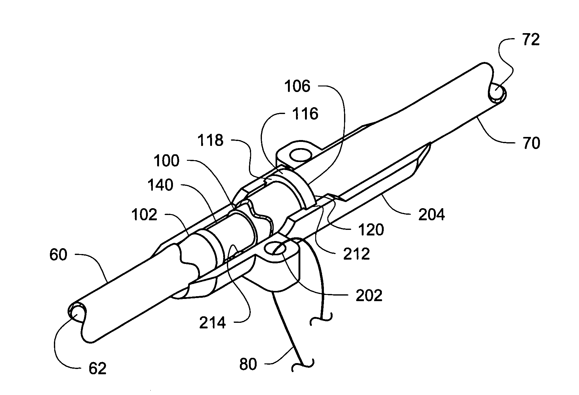
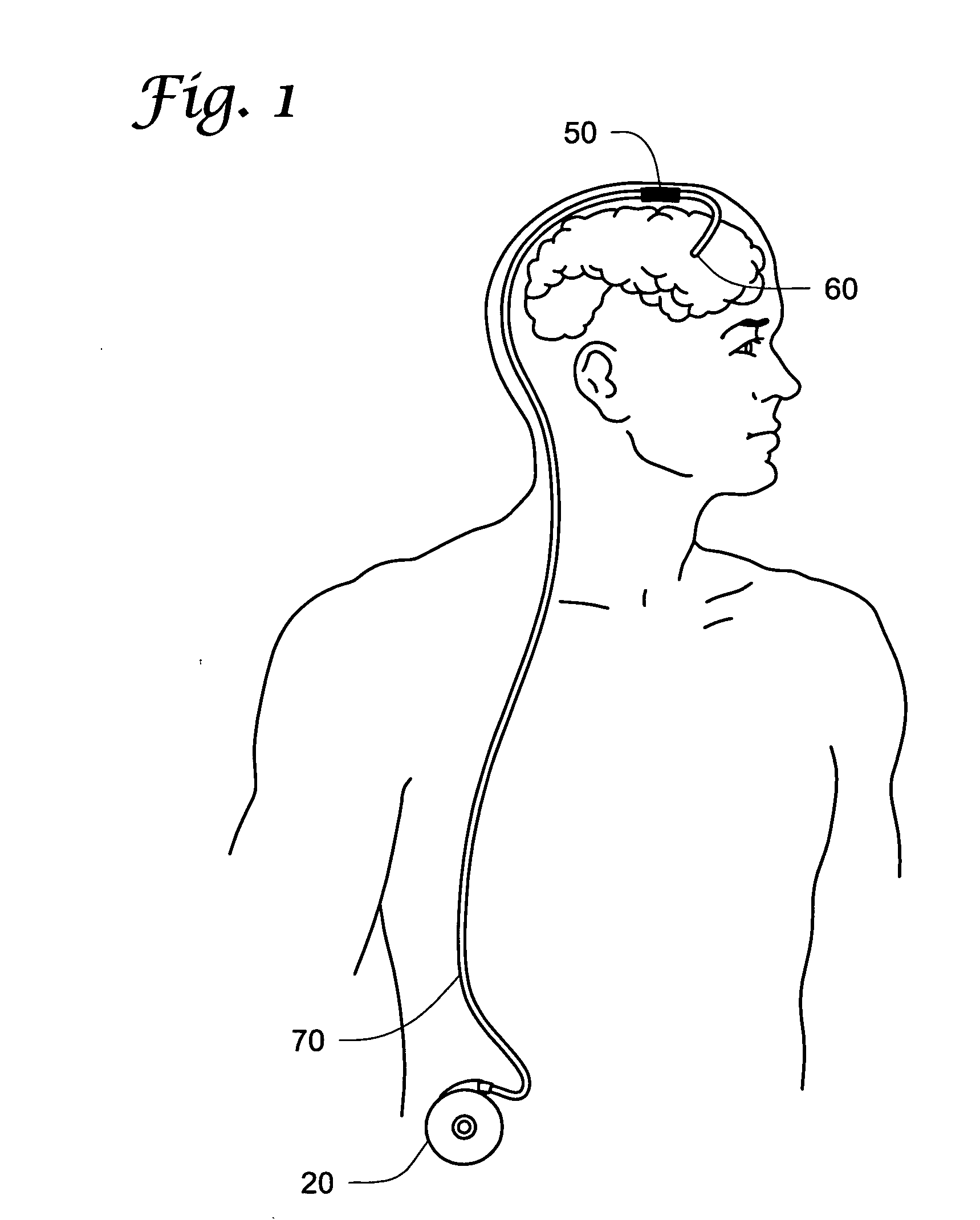
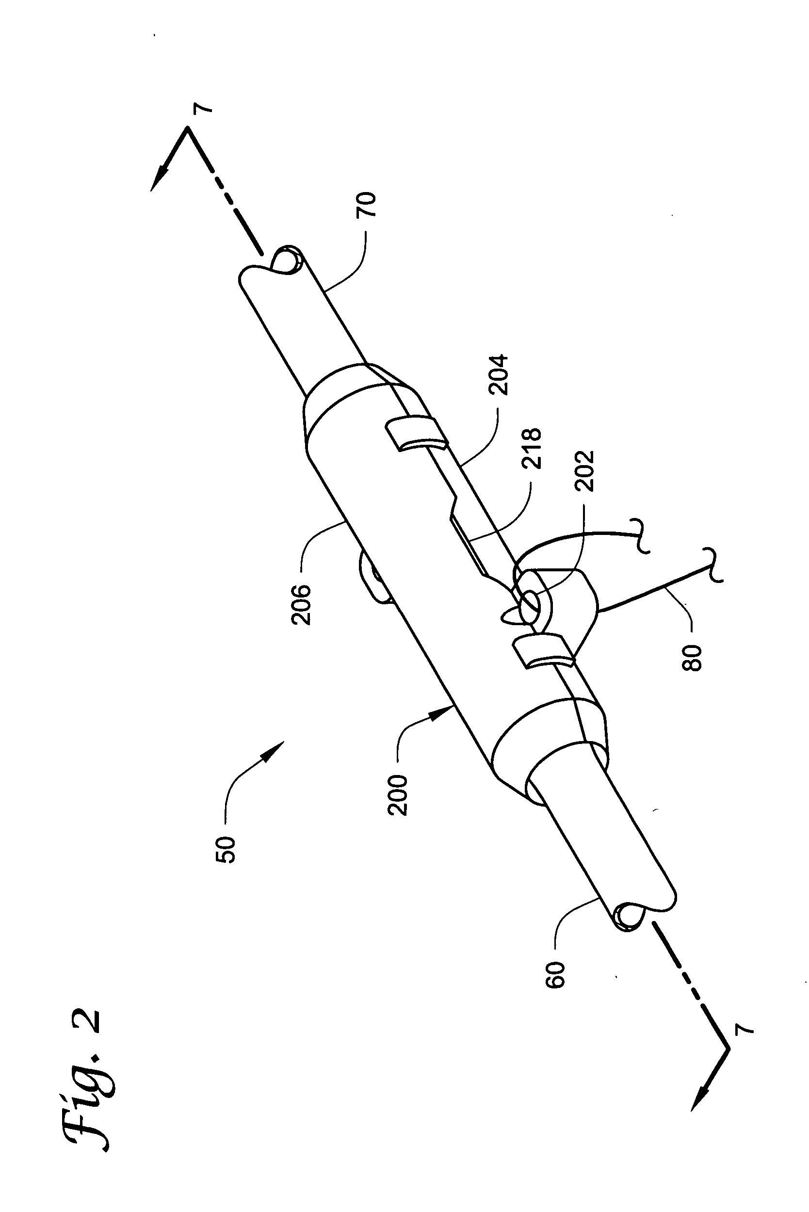
[0025] The invention is directed generally to apparatus and methods for securely coupling two pieces of tubing to one another. For example, embodiments of the present invention may be especially well-suited for joining separate sections of medical tubing, e.g., separate implantable catheters. In an embodiment of the present invention illustrated diagrammatically in FIG. 1, a connector assembly 50 for coupling a distal s...


PUM

PropertyMeasurementUnit
Lengthaaaaaaaaaa
Shapeaaaaaaaaaa
Polymericaaaaaaaaaa

Abstract

A connector assembly for interconnecting separate sections of tubing, e.g., catheters, and a method for using the same. Connector assemblies in accordance with embodiments of the present invention may be a two-piece construction having a connector pin and a strain relief device. The strain relief device, in addition to providing secure, substantially leak-free coupling of the tubing sections, may also provide strain relief to the tubing interconnection.

Description

TECHNICAL FIELD [0001] The present invention relates generally to medical devices and, more particularly, to strain relief devices and connector assemblies for joining two pieces of medical tubing, and to methods for using the same. BACKGROUND [0002] In many medical applications, it is necessary to connect one section of medical tubing, e.g., a catheter, with another. Generally speaking, it is important that these connections be relatively secure and stable so that the tubing does not separate or develop leaks at the connection point. Security and leak-resistance take on special importance in applications where the tubing sections are implanted in a human body. [0003] One procedure that necessitates implantation of medical tubing into the body involves the use of an implantable drug infusion pump. Such pumps are often used to control pain and / or spasticity, as well as to provide one or more drugs or fluid medications to a particular location within the body. For instance, a typical ...

Claims


Application Information

Patent Timeline
IPC IPC(8): A61M25/16
CPCA61M39/1011A61M2039/1044A61M2039/1088
Inventor CROSS, THOMAS E. JR.
Owner MEDTRONIC INC
Learn More