
Plasmon resonant structure, controlling method thereof, and a metallic domain manufacturing method

Inactive Publication Date: 2006-08-31
SAITO
View PDF1 Cites 11 Cited by
  • Summary
  • Abstract
  • Description
  • Claims
  • Application Information

AI Technical Summary

Benefits of technology

[0006] In view of the foregoing, the present invention intends to favorably control the plasmon resonance in the direction of the thickness of a structure and a direction orthogonal thereto. The invention further intends to control the plasmon resonance and improve the effect of filed enhancement thereof.
[0012] Accordingly, plasmon resonance can be controlled favorably and the effect of field enhancement can be improved.

Problems solved by technology

However, in a plasmon resonant film obtained by the chemical method described above, nanoparticles are in a state dispersed at random in a three-dimensional manner and the plasmon resonance can not be controlled by separate modes in the direction of the film thickness and the direction orthogonal thereto.
Accordingly, the effect of field enhancement by the plasmon has not been used efficiently.

Method used


Image

  • Plasmon resonant structure, controlling method thereof, and a metallic domain manufacturing method
  • Plasmon resonant structure, controlling method thereof, and a metallic domain manufacturing method
  • Plasmon resonant structure, controlling method thereof, and a metallic domain manufacturing method

Examples


example 1

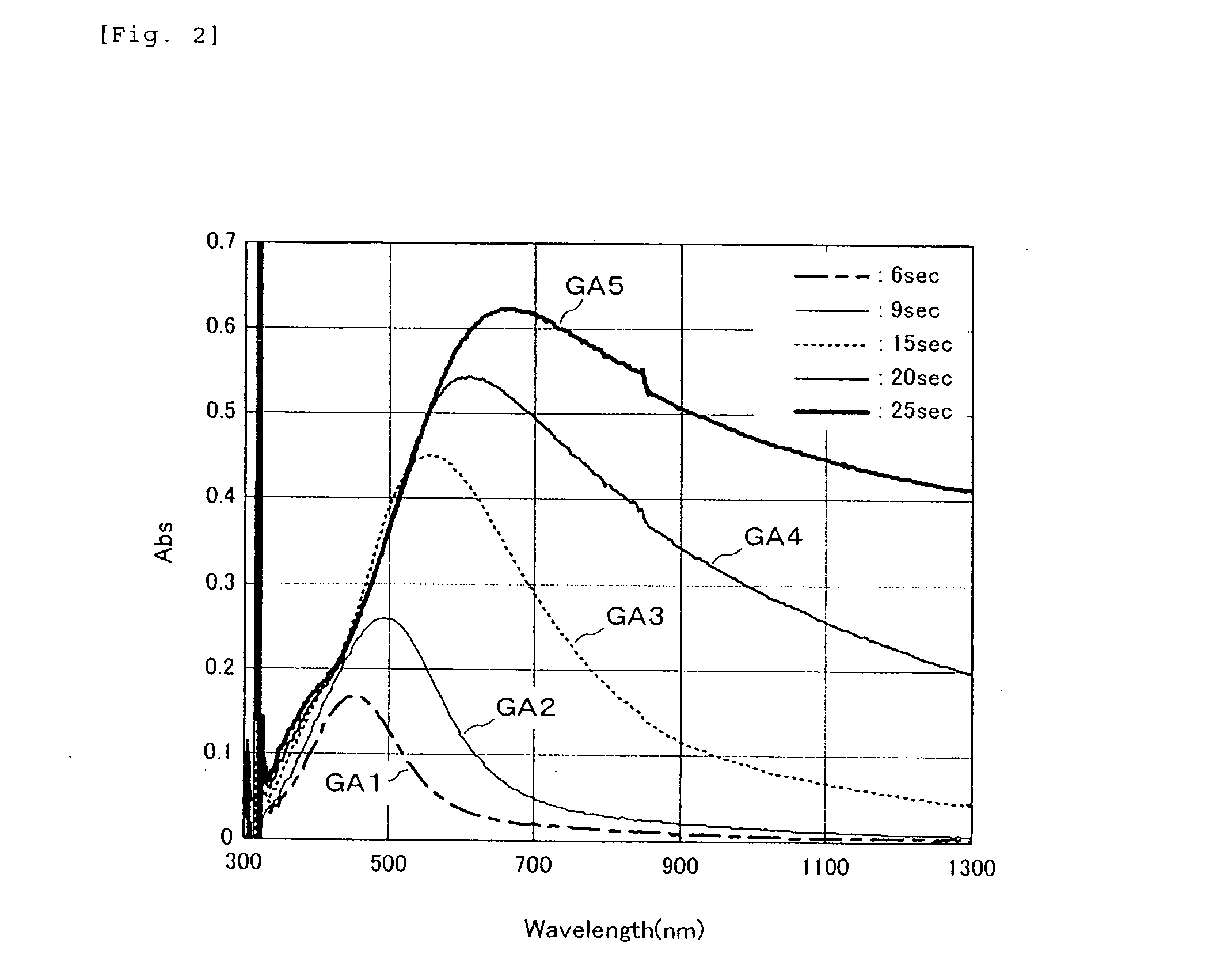
[0021] Example 1 of the invention is to be described at first with reference to FIG. 1 to FIG. 6. FIG. 1A shows a cross sectional structure of a plasmon resonance structure in this example. As shown in the drawing, a dielectric layer 10 has a structure in which layers 12 of nanoparticles or metallic domains 14 (hereinafter both of them are collectively referred to as “metallic domain”) are laminated each at an appropriate distance in the horizontal direction of the drawing. The metallic particle layer 12 has a constitution in which the metallic domains 14 are arranged being spaced apart from each other within a horizontal plane. As the dielectric layer 10, SiO2 is used for example. Further, as the metallic domain 14, a metal such as Au, Ag, or Al can be used.

[0022] While known methods may be used for forming the domain structure, it is formed, for example, by the method shown in FIGS. 1B to 1D. At first, as shown in FIG. 1B, metallic particles 14A for an SiO2 layer 10A are formed o...

example 2

[0047] Then, Example 2 of the invention is to be described with reference to FIG. 7. In this example, an existent plasmon resonant structure using a sol-gel method shown in FIG. 7(A) was formed by lamination at a predetermined distance in a dielectric film as shown in FIG. 7(B). That is, a plasmon resonant layer 802 by a sol-gel method was formed over a dielectric layer 800 and, further, a dielectric layer 804, a plasmon resonance layer 806, and a dielectric layer 808 were formed successively thereover by lamination to prepare a plasmon resonant structure. An effect due to the multi-layered structure can be utilized by changing the distance between the plasmon resonant layers 802 and 806.

[0048] The present invention is not restricted to the examples described above but can be modified variously within a range not departing from the gist of the invention.

[0049] According to the invention, since the plasmon resonance in the direction of the thickness of the plasmon resonance structu...


PUM


Abstract

Metallic particle layers with metallic domains being arranged therein each at a predetermined space within a horizontal plane are laminated at an appropriate distance in the vertical direction in a dielectric layer. The distance ΔW between each of the metallic domains may be controlled by controlling the growth of metallic particles for the horizontal direction and the distance ΔL between the metallic particle layers may be controlled by controlling the thickness of the dielectric layer to be laminated for the vertical direction, so that the effect of field enhancement by plasmon resonance is improved by satisfactory control for the plasmon resonance in the direction of the thickness and in the direction orthogonal thereto.

Description

BACKGROUND OF THE INVENTION [0001] 1. Field of the Invention [0002] The present invention concerns a plasmon resonance structure, a controlling method thereof and a metallic domain manufacturing method and, more specifically, it relates to plasmon resonance control. [0003] 2. Description of the Related Art [0004] In near field optics, it has been devised to unitize the effect of field enhancement, etc. by utilizing surface plasmon resonance and studies have been made on applications of various fields such as communication and recording media (Applied Physics, Vol 73, No. 10 (2004) “Propagation of Spreading of Surface Plasmon Polariton and Control”, p 1275-1284). For the effect of field enhancement, fine particles of from several nm to several hundreds of nm (hereinafter referred to as “nanoparticles”) are formed and the localized surface plasmon generated in the vicinity thereof is utilized. The nanoparticles are usually formed by a chemical method, for example, a sol-gel method and...

Claims


Application Information

Patent Timeline
IPC IPC(8): C12M1/34G01N1/28G01N33/543
CPCG01N21/554G01N33/54373
Inventor SAITO
Owner SAITO
Learn More