
System and method for generating optical return-to-zero signals with alternating bi-phase shift and frequency chirp

a technology of frequency chirp and biphase shift, which is applied in the field of generating optical return-to-zero signals with alternating biphase shift and frequency chirp, can solve the problems of expensive and complex conventional systems for generating these rz signals, and achieve the effects of improving reliability, reducing complexity of transmitters, and reducing transmitter costs

Active Publication Date: 2006-08-31
FUTUREWEI TECH INC
View PDF7 Cites 10 Cited by
  • Summary
  • Abstract
  • Description
  • Claims
  • Application Information

AI Technical Summary

Benefits of technology

The present invention provides systems and methods for generating optical chirped return-to-zero (CRZ) signals with negative frequency chirp. This can improve the performance of fiber optical transport systems and reduce the cost of a transmitter for optical CRZ signals. The invention uses only components designed for NRZ transmitters and can lower the complexity of a transmitter for optical CRZ signals. The invention also provides optical CRZ signals with positive frequency chirp that enhance signal resistance to distortions caused by nonlinear effects experienced during transmission. Overall, the invention offers improved reliability and performance for fiber optical transport systems.

Problems solved by technology

But the conventional systems for generating these RZ signals often are complex and expensive.

Method used


Image

  • System and method for generating optical return-to-zero signals with alternating bi-phase shift and frequency chirp
  • System and method for generating optical return-to-zero signals with alternating bi-phase shift and frequency chirp
  • System and method for generating optical return-to-zero signals with alternating bi-phase shift and frequency chirp

Examples


Embodiment Construction

[0036] The present invention relates in general to telecommunication techniques. More particularly, the invention provides a system and method for generating optical return-to-zero signals with alternating bi-phase shift and frequency chirp. Merely by way of example, the invention is described as it applies to optical networks, but it should be recognized that the invention has a broader range of applicability.

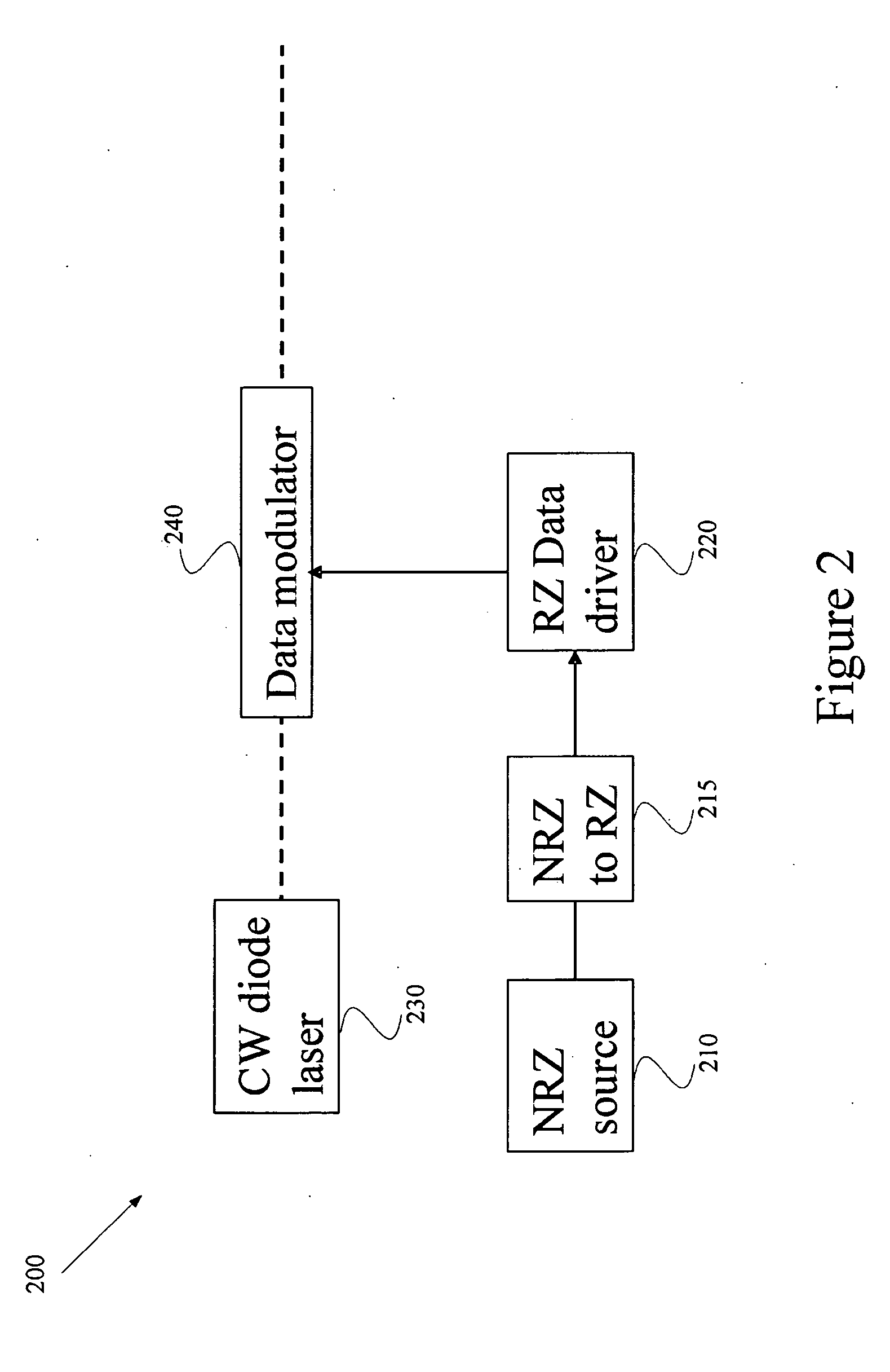
[0037] As shown in FIG. 2, the system 200 performs optical RZ modulations by generating RZ driving signals in electrical domain. The RZ pulses often occupy 50%, or less, of the bit period. Consequently, the generation of electrical RZ driving signals often needs to use circuit devices that have a radio-frequency (RF) bandwidth twice as wide as that needed for an NRZ electrical circuit. These wide-band components, such as wide-band drivers and / or wide-band amplifiers, usually are more expensive than the corresponding NRZ components. Additionally, the converter between electric...


PUM

PropertyMeasurementUnit
optical returnaaaaaaaaaa
electricalaaaaaaaaaa
signal strengthaaaaaaaaaa

Abstract

A system and method for generating an optical return-to-zero signal with frequency chirp. The system includes a bit separator configured to receive an electrical non-return-to-zero signal and generate a first input signal and a second input signal. Additionally, the system includes a first driver configured to receive the first input signal and generate a first driving signal. The first driving signal is proportional to the first input signal in signal strength. Moreover, the system includes a second driver configured to receive the second input signal and generate a second driving signal. The second driving signal is proportional to the second input signal in signal strength. Also, the system includes a light source configured to generate a light, and an electro-optical modulator.

Description

CROSS-REFERENCES TO RELATED APPLICATIONS [0001] This application claims priority to U.S. Provisional Application No. 60 / 656,610, filed Feb. 25, 2005, which is incorporated by reference herein. [0002] The following two commonly-owned co-pending applications, including this one, are being filed concurrently and the other one is hereby incorporated by reference in its entirety for all purposes: [0003] 1. U.S. patent application Ser. No. ______, in the name of Yu Sheng Bai, titled, “System and Method for Generating Optical Return-to-Zero Signals with Alternating Bi-Phase Shift,” (Attorney Docket Number 021822-001110US); and [0004] 2. U.S. patent application Ser. No. ______, in the name of Yu Sheng Bai, titled, “System and Method for Generating Optical Return-to-Zero Signals with Alternating Bi-Phase Shift and Frequency Chirp,” (Attorney Docket Number 021822-001120US).STATEMENT AS TO RIGHTS TO INVENTIONS MADE UNDER FEDERALLY SPONSORED RESEARCH OR DEVELOPMENT [0005] NOT APPLICABLE REFEREN...

Claims


Application Information

Patent Timeline
Patent Type & Authority Applications(United States)
IPC IPC(8): G11B7/005
CPCH04B10/5051H04B10/5055H04B10/508H04B10/58
Inventor BAI, YU SHENG
Owner FUTUREWEI TECH INC
Learn More