
Soalr energy water heater

a solar energy and water heater technology, applied in solar heat systems, sustainable buildings, light and heating equipment, etc., can solve the problems of low efficiency of conventional inability to normally function water systems, and inability to meet the ever-increasing demand of solar energy water heaters, so as to achieve heat up the water and save costs

Inactive Publication Date: 2006-08-31
XIA JUN +1
View PDF9 Cites 15 Cited by
  • Summary
  • Abstract
  • Description
  • Claims
  • Application Information

AI Technical Summary

Benefits of technology

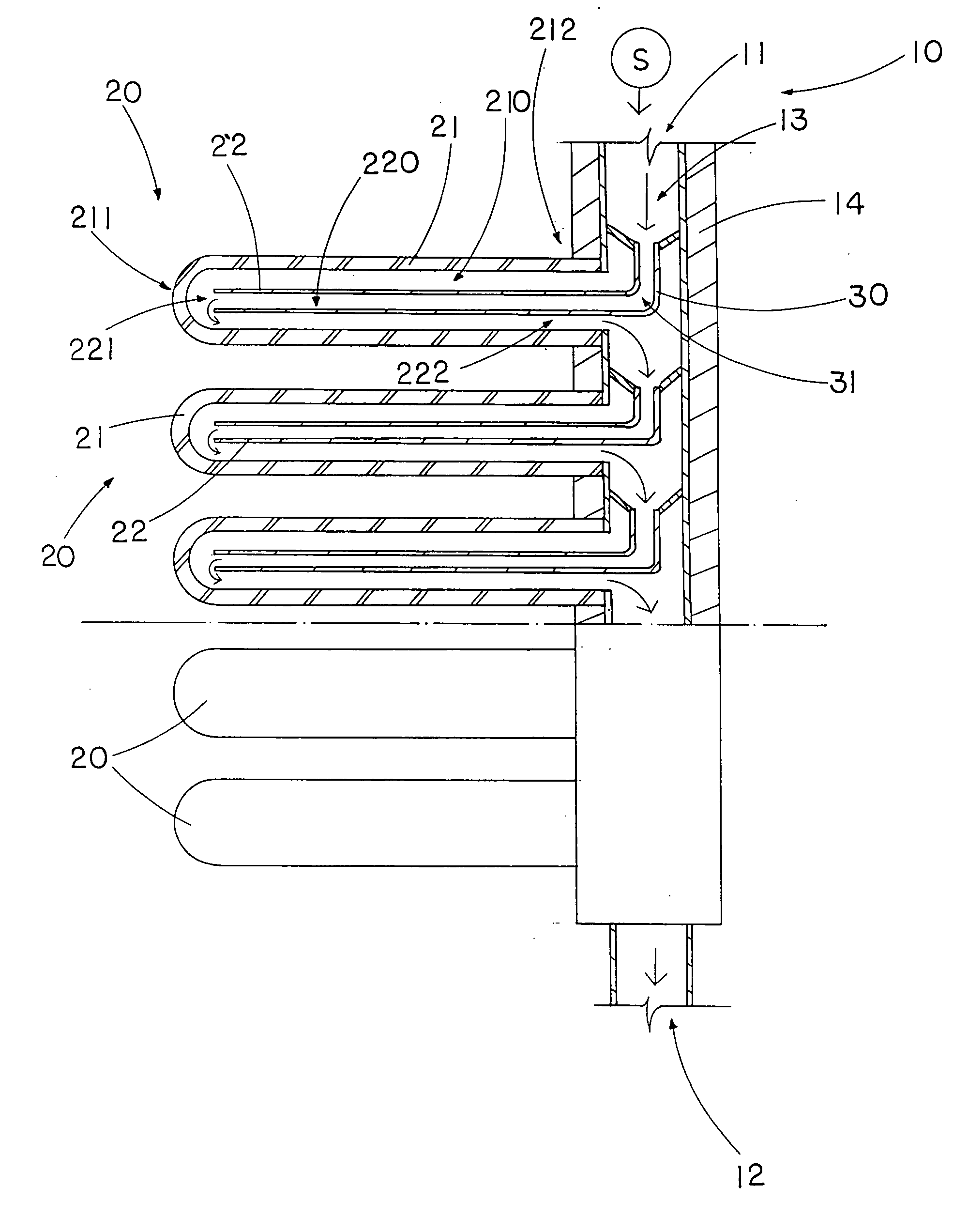
[0009] A main object of the present invention is to provide a solar energy water heater, wherein the water is guided to circularly flow within each of the heat collecting tubes to substantially heat up the water therewithin by solar energy while being cost effective.
[0010] Another object of the present invention is to provide a solar energy water heater, wherein the heat collecting tubes are radially extended from a water pipe such that the water flows from a water inlet of the water pipe to a water outlet thereof through each of the heat collecting tubes to enhance the heat exchange process.
[0012] Another object of the present invention is to provide a solar energy water heater, which can be located at any position to optimize the sun orientation for effectively transforming solar energy into heat energy.
[0014] Another object of the present invention is to provide a solar energy water heater, which does not involve complicated mechanical components so as to minimize the manufacturing cost and the ultimate selling price of the present invention.
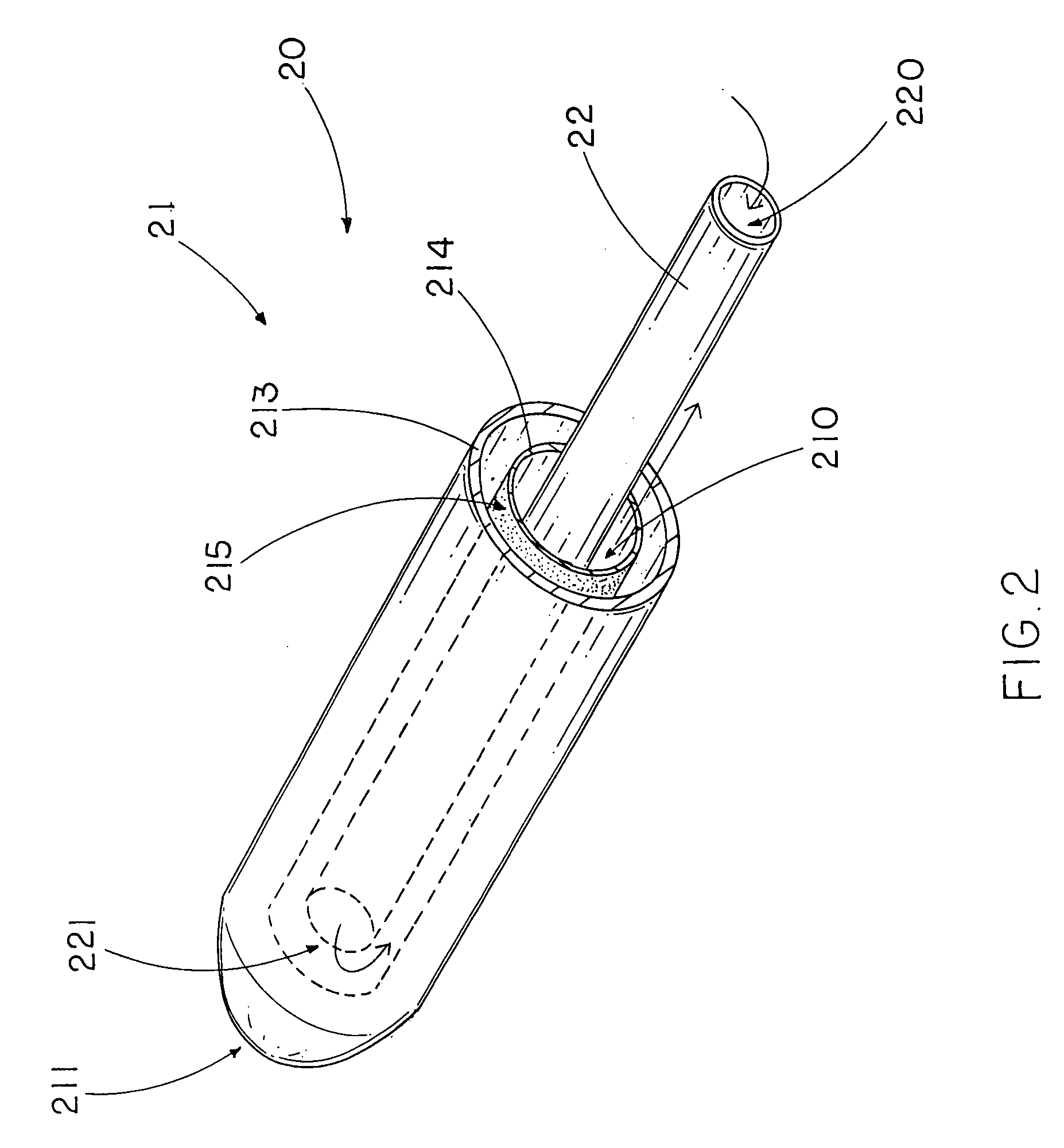
[0019] a heat transferring tube, which is made of heat conductive material, disposed in the heat collecting tube to define a water conduit between the heat collecting tube and the heat collecting tube, wherein the heat transferring tube has a water channel and an outer opening end extended towards to the outer closed end of the heat collecting tube to communicate the water channel with the water conduit of the heat collecting tube such that the water is guided to flow from the water inlet to each of the solar heat units to circularly flow between the water conduit and the water channel thereof so as to substantially heat up the water at each of the solar heat units before flowing out at the water outlet of the water pipe.

Problems solved by technology

Those solar energy water heaters no doubt meet the ever-increasing demand of environmental protection and ‘clean energy source’ from people all over the world.
It is worth to mention that the hot water is collected at the upper portion of the heat collecting tube to a water tank while the cool water is remained at the lower portion of the heat collecting tube such that the efficiency of the conventional solar energy water heater is very low.
Furthermore, the water system cannot be normally functioned during the heat exchange of the water.
Therefore, the solar energy water heater cannot be functioned under the normal water pressure of the water system since the water must be collected within the heat collecting tube for heat exchange.
Therefore, the installation of the solar energy water heater is limited by the position of the heat collecting tube that the heat collecting tube must be located at an optimized orientation under the sunlight.
It is worth to mention that the temperature of the heat collecting tube is relatively high in order to heat up the water therewithin such that when the cool water is filled into the heat collecting tube, the glass made heat collecting tube will be cracked due to the sudden change of temperature.
Once the heat collecting tube is broken, the entire solar energy water heater cannot be functioned.

Method used


Image

  • Soalr energy water heater
  • Soalr energy water heater
  • Soalr energy water heater

Examples


second embodiment

[0042] the two heat transferring tubes 22′ of each pair of the solar heat units 20′ are integrally extended to form an elongated tubular structure through the water pipe 10′ so as to communicate the water channels 220′ with each other such that the water is guided to flow to each pair of the solar heat units 20′ in a zigzag manner that the water flows into the water conduit 210′ of one of the solar heat units 20′ from the water pipe 10′ and then flow into the water channels 220′ to another solar heat unit 20′ so as to return back to the water pipe 10′ through the water conduit 210′ of the respective solar heat unit 20′, as shown in FIG. 3.

[0043] The solar energy water heater further comprises a plurality of water guiders 30′ spacedly disposed in the water passage 13′ of the water pipe 10′ to align with the pairs of solar heat units 20′ respectively, wherein each of the water guiders 30′ has a guiding passage 31′ extended to the inner opened end 212′ of the respective heat collectin...

third embodiment

[0051] the water pipe 10″ comprises a plurality of tubular bodies 101″ coaxially mounted with each other to form the water passage 13″ wherein each of the tubular bodies 101″ is positioned between each pair of the solar heat units 20″ such that the solar energy water heater of the present invention is adapted to be easily assembled or disassembled for transportation and storage.


PUM


Abstract

A solar energy water heater includes a water pipe and a plurality of solar heat units transversely extended from the water pipe, wherein each solar heat unit includes a heat collecting tube is adapted for heating up the water within the heat collecting tube and a heat transferring tube disposed in the heat collecting tube to define a water conduit. The heat transferring tube has a water channel and an outer opening end extended towards to an outer closed end of the heat collecting tube to communicate the water channel with the water conduit of the heat collecting tube such that the water is guided to flow from the water inlet to each of the solar heat units to circularly flow between the water conduit and the water channel thereof so as to substantially heat up the water before flowing out at a water outlet of the water pipe.

Description

BACKGROUND OF THE PRESENT INVENTION [0001] 1. Field of Invention [0002] The present invention relates to a water heater, and more particularly to a solar energy water heater, wherein the water is guided to circularly flow within each of heat collecting tubes to substantially heat up the water therewithin by solar energy while being cost effective. [0003] 2. Description of Related Arts [0004] Conventional water heaters mainly utilize gas or electricity as a power source to heat up water for domestic or industrial purpose. A conventional water heating system comprises a water heater having a water outlet and a water inlet connecting with a water source in such a manner that the water at the room temperature is heated up by the water heater to reach a preset temperature. [0005] Water heater utilizing solar energy as the power source has been developed to resolve the problems of potential energy crises or shortages. Those solar energy water heaters no doubt meet the ever-increasing dema...

Claims


Application Information

Patent Timeline
Patent Type & Authority Applications(United States)
IPC IPC(8): F24J2/04
CPCF24J2/245F24J2/4647Y02B10/20Y02E10/44F24S80/30F24S10/45F24S10/742
Inventor XIA, JUNXIA, ZHU SHENG
Owner XIA JUN
Learn More