Image output and input systems

a technology of image output and input system, which is applied in the field of image output/input system, can solve the problems of limited error range of vertical synchronous signal error, and achieve the effect of reducing cost and removing image flicker and color error

Inactive Publication Date: 2006-08-24
SONIX TECH
View PDF13 Cites 10 Cited by
  • Summary
  • Abstract
  • Description
  • Claims
  • Application Information

AI Technical Summary

Benefits of technology

[0010] Through the design of the invention, the image output / input system uses the sensor / video period compensation unit to compensate the period of the vertical synchronous signal from the image synchronous signal generator in reference to a digital signal. Hence, the error of the vertical synchronous signal is limited in a very small range, and the vertical synchronous signal is synchronized with the frequency and phase of the analog signal. Since the vertical synchronous signal is synchronized with the analog signal in frequency and phase, the sensor timing generator may generate the sensor control timing that is synchronized with the analog signal, and the sensor control timing for the sensor is used as a reference to decide the time point of exposure. Accordingly, the time point of exposure for the sensor is synchronized with the analog signal and further synchronized with the frequency and phase of the artificial light source to eliminate the image flicker and color error.
[0011] Also, since the overall image output / input system operates in reference to an identical system clock, the video encoder may deal with the integration and encoding of the luminance, chroma, burst, and synchronization at a time. Hence, the image output / input system needs only one digital to analog converter and thus has a reduced cost.

Problems solved by technology

Hence, the error of the vertical synchronous signal is limited in a very small range, and the vertical synchronous signal is synchronized with the frequency and phase of the analog signal.

Method used


Image

  • Image output and input systems
  • Image output and input systems
  • Image output and input systems

Examples


Embodiment Construction

[0020] The image output / input system according to the invention will be described with reference to the accompanying drawings.

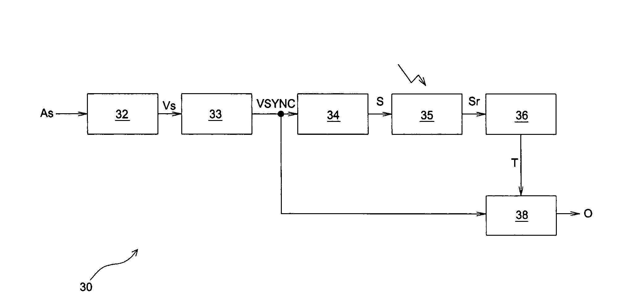
[0021]FIG. 3 shows a block diagram illustrating an image output / input system according to the invention. The image output / input system 30 includes a voltage comparator 32, a sensor / video period compensation unit 33, a sensor timing generator 34, a sensor 35, an image / color processing unit 36, and a video encoder 38. Note that all components in the image output / input system 30 operate in reference to the original system clock, which is different compared to conventional image output / input system 10. Hence, the system clock received by each component is not additionally indicated in FIG. 3.

[0022] The voltage comparator 32 receives an analog signal As and then converts it into a digital signal Vs whose frequency and phase are synchronized with that of the analog signal As. The voltage comparator 32, well known in the art and thus not explaining in detail, may ...


PUM


Abstract

An image output/input system includes a phase comparator, an image synchronous signal generator, a sensor timing generator, a sensor, an image/color processing unit, and a video encoder. The phase comparator receives a digital signal and a vertical synchronous signal and compares their period and phase to generate a clock correction signal. The image synchronous signal generator receives the clock correction signal and adjusts a subsequent period of the vertical synchronous signal according to the clock correction signal. The sensor timing generator receives the vertical synchronous signal and generates the sensor control timing, and the sensor receives the sensor control timing and generates raw image data. The image/color processing unit receives the raw image data and deals with the image and color process of the raw image data to generate target image data. The video encoder receives the vertical synchronous signal and the target image data and encodes them to generate analog encoded image data.

Description

FIELD OF THE INVENTION [0001] The invention relates to an image processing system, and, more particularly, to an image output / input system DESCRIPTION OF THE RELATED ART [0002]FIG. 1 shows a block diagram illustrating a typical image output / input system. Referring to FIG. 1, the image output / input system 10 includes a voltage comparator 12, a phase locked loop 13, an image synchronous signal generator 133, a sensor-timing generator 14, a sensor 15, an image / color processing unit 16, a timing generator 17, and a video encoder 18. Note that, in the image output / input system 10, a output clock signal P1 generated from the phase locked loop 13 and synchronized with a power source (alternating current) 11 is fed to the image synchronous signal generator 133, the sensor-timing generator 14, the image / color processing unit 16, and the video encoder 18 to replace the system clock adopted in a typical digital system. Hence, the image synchronous signal generator 133, the sensor-timing genera...

Claims


Application Information

Patent Timeline
Patent Type & Authority Applications(United States)
IPC IPC(8): H04N5/04H04N5/243
CPCH04N5/2353H04N9/455H04N23/73H04N5/04H04N25/00H04N25/75
Inventor TSAI, CHIA-LIN
Owner SONIX TECH
Why Eureka
Try Eureka