Portable articulating tool support

Active Publication Date: 2006-08-24
EKSO BIONICS
View PDF10 Cites 33 Cited by
  • Summary
  • Abstract
  • Description
  • Claims
  • Application Information

AI Technical Summary

Benefits of technology

[0007] It is an object of the present invention, at least in preferred forms, to provide a portable articulating support for improving ease-of-use of hand-operated power tools within and throughout three-dimensional work spaces, and which can be quickly assembled for use, then disassembled for storage or transport.
[0008] According to one aspect of the present invention, there is provided a portable articulating support apparatus for supporting a hand-manipulated power tool while allowing movement of the tool in three dimensions, the apparatus comprising: a mounting device for the apparatus capable of disengageable attachment to a support element, one or more hinge members each having two spaced, parallel bores for receiving hinge pins therein; a tool holder capable of engaging and supporting a hand-operated power tool while allowing swivelling of said tool about horizontal and vertical axes; one or more spacer elements; a counterbalance element having opposite ends, with one end detachably engaged with one said hinge member and an opposite end engaged with the tool holder, said opposite end being movable in a vertical plane while said one end is supported by said one hinge member, and having a balancing arrangement generating a force counteracting weight applied to said one end by said tool holder. A portable articulating support apparatus for supporting a hand-manipulated power tool while allowing movement of the tool in three dimensions, the apparatus condensing: a mounting device for the apparatus capable of disengageable attachment to a support element; one or more hinge members each having two spaced, parallel bores for receiving hinge pins therein; a tool holder capable of engaging and supporting a hand-operated power tool while allowing swivelling of said tool about horizontal and vertical axes; one or more spacer elements; a counterbalance element having opposite ends, with one end detachably engaged with one said hinge member and an opposite end engaged with the tool holder, said opposite end being movable in a vertical plane while said one end is supported by said one hinge member, and having a balancing arrangement generating a force counteracting weight applied to said one end by said tool holder, wherein said mounting device, said one or more spacer elements, said one or more hinge members and said counterbalance element are arranged to form inter parts of an articulating arm having said mounting device at one end of the articulating arm, said counterbalance element at an opposite end of the articulating arm, and said one or more spacer elements and said one or more hinge members alternating therebetween; and a plurality of vertically disposed hinge pins passing trough vertically aligned bores, including said spaced, parallel bores of said one or more hinge member, in said interconnecting parts of said articulating arm to allow pivotal rotation of said parts around said hinge pins, at least one of said hinge pins being slidably removable from one said bores and having an enlarged head at an upper end thereof shaped to be graspable by hand to facilitate complete removal of said pin, thereby allowing at least partial disasembly of said articulating arm for ease of transportation of said apparatus.
[0009] According to another aspect of the invention, there is provided portable articulating support apparatus for supporting a hand-operated power tool while allowing movement of the tool in three dimensions, the apparatus comprising: a mounting device capable of disengageable attachment to a support element; a hinge member having two juxtaposed bores for receiving hinge pins therethrough; a tool holder capable of engaging and supporting a hand-operated power tool while allowing swivelling of said tool about lace and vertical axes, a spacer arm having opposite ends with one end detachably engaged with the mounting device, and another end detachably engaged with the hinge member; and a counterbalance arm having opposite ends, with one end detachably engaged with the hinge member and an opposite end detachably engaged with the tool holder, said opposite end being movable in a vertical plane while said one end is supported by said hinge element, and having a balancing arrangement generating a force counteracting weight applied to said one end by said tool holder; wherein said mounting device, spacer arm, hinge member and counterbalance arm are detachably and rotatably engaged one with another by a plurality of removable vertically disposed hinge pins passing through vertically aligned bores in overlapping parts of said mounting device, spacer arm, hinge member and counterbalance arm, said removable hinge pins having enlarged heads at upper ends thereof shaped to be graspable by hand to facilitate complete removal of the pins from said bores, thereby allowing separation of said mounting device, spacer arm, hinge member and counterbalance arm for ease of replacement, storage and transport thereof.
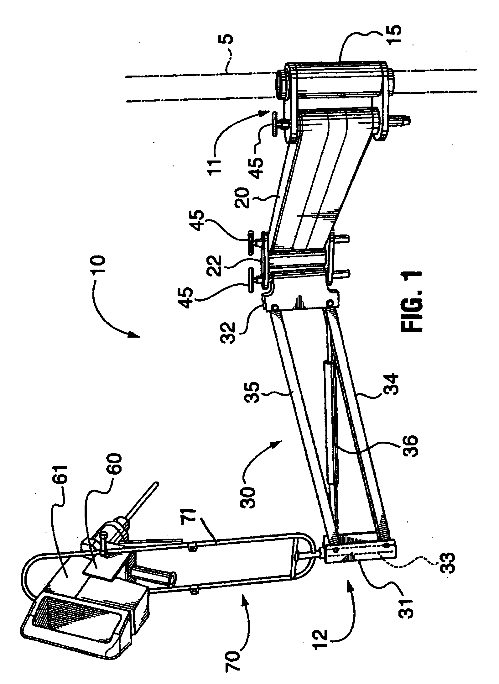
[0011] In a preferred form, the invention provides a multiple-component articulating tool support wherein the components are detachably engaged with removable hinge pins. The tool support has a proximal end and a distal end wherein a clamping device is provided at the proximal end for demountably engaging a structural support element, and a vertically disposed counterbalance arm assembly is provided at the distal end for slidingly receiving and supporting therein a tool-bearing member. The counterbalance arm assembly is preferably provided with a gas-charged cylinder for balancing and supporting the weight of a hand-operated power tool and is confirmed to pivotably move in a vertical axis. There is also provided a double-link hinge component configured to receive therethrough two opposing removable hinge pins for detachably engaging the counterbalance arm assembly and one or more spacer arms intermediate the clamping device. The spacer arm can be detachably engaged with the clamping device or alternatively, the spacer arm can be detachably engaged to a double-link hinge which is also detachably engaged with the clamping device. The components of this invention can easily be moved rotatably around the removable hinge pins by which they are detachably engaged so that the components can be folded tightly together, tally folded, or unfolded so that the combination of components form a straight line. A hand-operated power tool mounted in the tool bearing member can easily be moved, orientated, manipulated, and operated within and throughout a three-dimensional workspace with minimal physical exertion.

Problems solved by technology

Such tools typically generate considerable torque and vibratory forces which are transmitted to the operators' hands, arms and bodies making precise manipulation of die tools difficult.
Extended operation of such tools in these positions may cause muscle fatigue and / or numbness in the operators' bands and arms hereby acting not only operator efficiency, but also their safe handling of the tools.
Furthermore, the nature of uses to which such tools are applied often result in the tools being inadvertently jammed, stuck or deflected thereby causing unexpected transmission of torque forces that may cause operators to lose their balance resulting in twisting of their bodies or falls causing injuries.
The rugged nature of the tool-engaging devices and their connection to the first members provide only limited operator-controlled positioning and manipulation of hand power tools relative to the first members.
Consequently, such supports arm not suitable for use in three-dimensional workspaces where space is restricted or limited and where the tools must be manipulated in multiple radial outward and upward orientations relative to the first member.
Another disadvantage is that, due to the permanent assembly of the parts, they can not be easily modified to extend or reduce their scope of movement through disassembly and the addition or removal of one or more members.
Furthermore, due to the secure fastenings required to attach the distal ends of the supports to structural members in order to provide stability to the supports when in use, they are not portable, i.e., quickly and easily dismounted form the structural member for transport.

Method used


Image

  • Portable articulating tool support
  • Portable articulating tool support
  • Portable articulating tool support

Examples


Embodiment Construction

[0029] As shown in FIG. 1 of the accompanying drawings, a preferred embodiment of the present invention comprises a portable, multi-component articulating support apparatus 10 for a hand-manipulated power tool 61, e.g. a rock dill as shown. The support 10 has a proximal end 11 and a distal end 12, and is equip with a mounting device 15 for detachable engagement with a support element 5 at proximal end 11. Mounting device 15 is detachably coupled to the proximal end of an elongated rigid spacer element 20 by means of a hinge pin 45, while the distal end of spacer element 20 is detachably coupled to one side of double-axis hinge element 22 by means of another hinge pin 45. The distal end 12 of support apparatus 10 includes an articulating elongated counterbalance element 30 detachably coupled to the other side of the double-axis hinge element 22 by means of another hinge pin 45. Articulating counterbalance element 30 has a distal bracket 31 and a proximal bracket 32, both pivotably co...


PUM

PropertyMeasurementUnit
Weightaaaaaaaaaa
Pressureaaaaaaaaaa

Abstract

A portable multiple-component articulating support apparatus for engaging, moving, orientating and manipulating a hand-operated power tool within and throughout a three-dimensional workspace. The apparatus includes a clamping device for demountable engagement with a structural element, an elongate double-link hinge member, a spacer arm having opposite ends adapted for detachable engagement and rotational communication with the clamping device and the double-link hinge member, a vertically disposed pivotably connected counterbalance arm assembly adapted for detachable engagement and rotational communication with the double-link hinge member. The counterbalance arm assembly is equipped with a gas-charged cylinder for balancing the weight of hand-operated power tools. The clamping device, spacer arm, double-link hinge and counterbalance arm assembly are interconnected with removable hinge pins. A tool-mounting bracket is provided for gripping engaging a power tool. The tool-mounting bracket pivotably engages a power tool-bearing member which slidingly and rotatably communicates with the counterbalance arm assembly.

Description

FIELD OF THE INVENTION [0001] The present invention relates to articulating supports for hand power tools, and more particularly, to portable articulating supports for manual-controlled movement and operation of hand power tools within and throughout three-dimensional work spaces. BACKGROUND OF THE INVENTION [0002] Electric and pneumatic-powered hand power tools such as jacks, hammer drills, air hammer, impact wrenches and reciprocating saws among others, are commonly used in co on and demolition industries, in heavy equipment repair, and in under-ground mining activities. The weights of these types of tools range between 4.5 kg (i.e., 10 lbs) to 22.7 kg (i.e., 50 lbs) and in some cases, e.g., jackhammers, may each 34 kg (i.e., 75 lbs) or more. Such tools typically generate considerable torque and vibratory forces which are transmitted to the operators' hands, arms and bodies making precise manipulation of die tools difficult. Quite often, it is necessary for operators to wield, man...

Claims


Application Information

Patent Timeline
IPC IPC(8): A47F5/00
CPCB25H1/0021F16M11/04F16M11/10F16M11/2014F16M11/2092F16M11/24Y10T408/865F16M13/022F16M2200/02F16M2200/044F16M2200/063Y10T16/5363F16M13/02
Inventor THIESSEN, GORDON DANIEL
Owner EKSO BIONICS
Why Eureka
Try Eureka