
Apparatus for monitoring pressure using capillary tubing

a technology of capillary tubing and apparatus, which is applied in the direction of fluid removal, survey, borehole/well accessories, etc., can solve the problem of reducing the likelihood of damage or loss to sensitive instruments during use, and achieve the effect of convenient maintenan

Inactive Publication Date: 2006-08-24
CONRAD GREG ALLEN
View PDF20 Cites 9 Cited by
  • Summary
  • Abstract
  • Description
  • Claims
  • Application Information

AI Technical Summary

Benefits of technology

[0019] The present invention is directed to an apparatus for continuously monitoring the flowing bottom hole pressure of a gas well. The invention is particularly well suited to use in CBM and other unconventional gas well configurations. The invention utilizes a capillary tube that runs along the exterior of the production tubing for the well. In this manner the delicate instrumentation associated with the measurement may be located at the other end of the capillary tube, preferably at the well head. This reduces the likelihood of damage or loss to sensitive instrumentation during use. It also simplifies maintenance with respect to the invention, since the tubing need not be removed if there is a need to replace or calibrate instrumentation.
[0023] It is a further object of the present invention to provide for a pressure monitoring apparatus and method that does not block the interior of the production tubing in a gas well.

Problems solved by technology

This reduces the likelihood of damage or loss to sensitive instrumentation during use.

Method used


Image

  • Apparatus for monitoring pressure using capillary tubing
  • Apparatus for monitoring pressure using capillary tubing
  • Apparatus for monitoring pressure using capillary tubing

Examples


Embodiment Construction

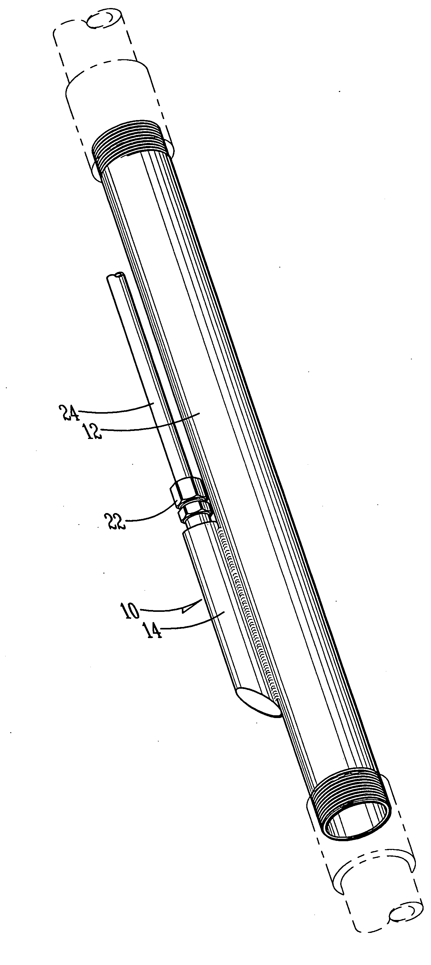
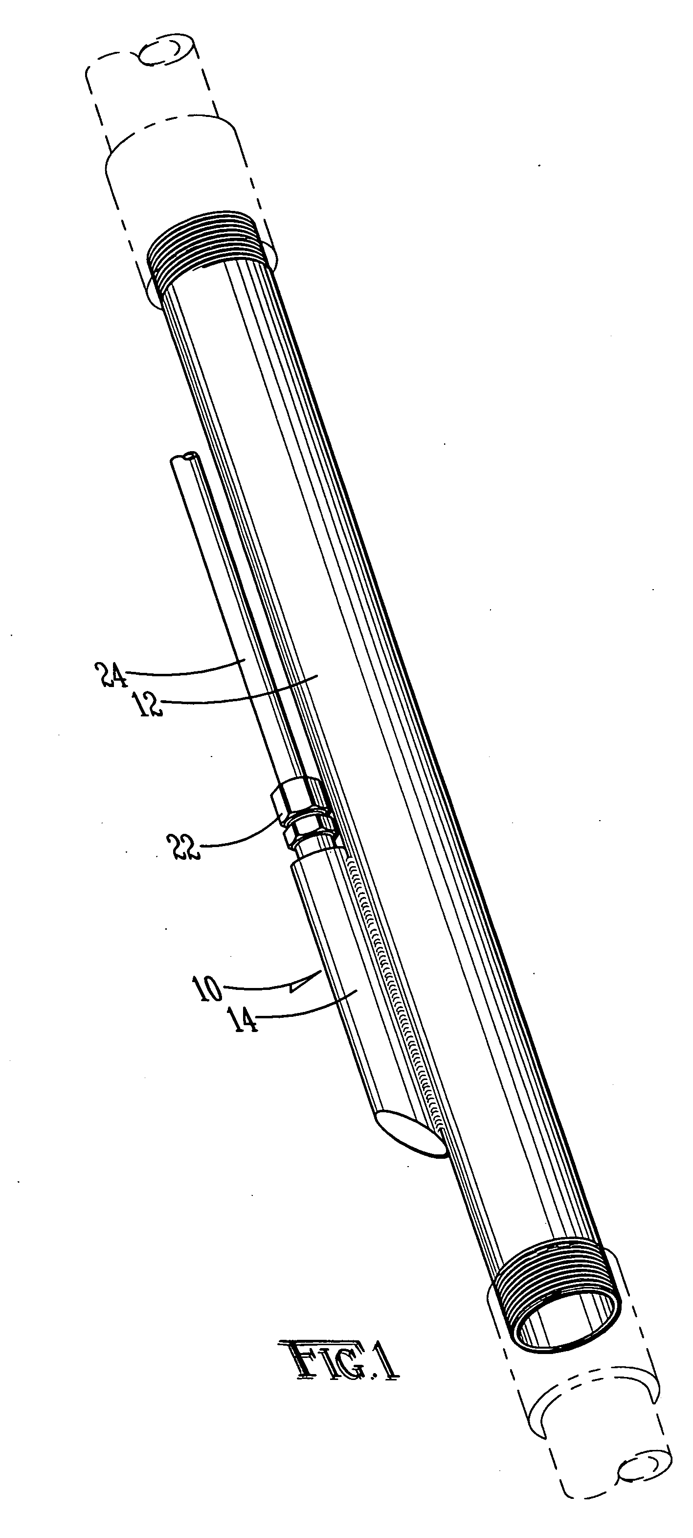
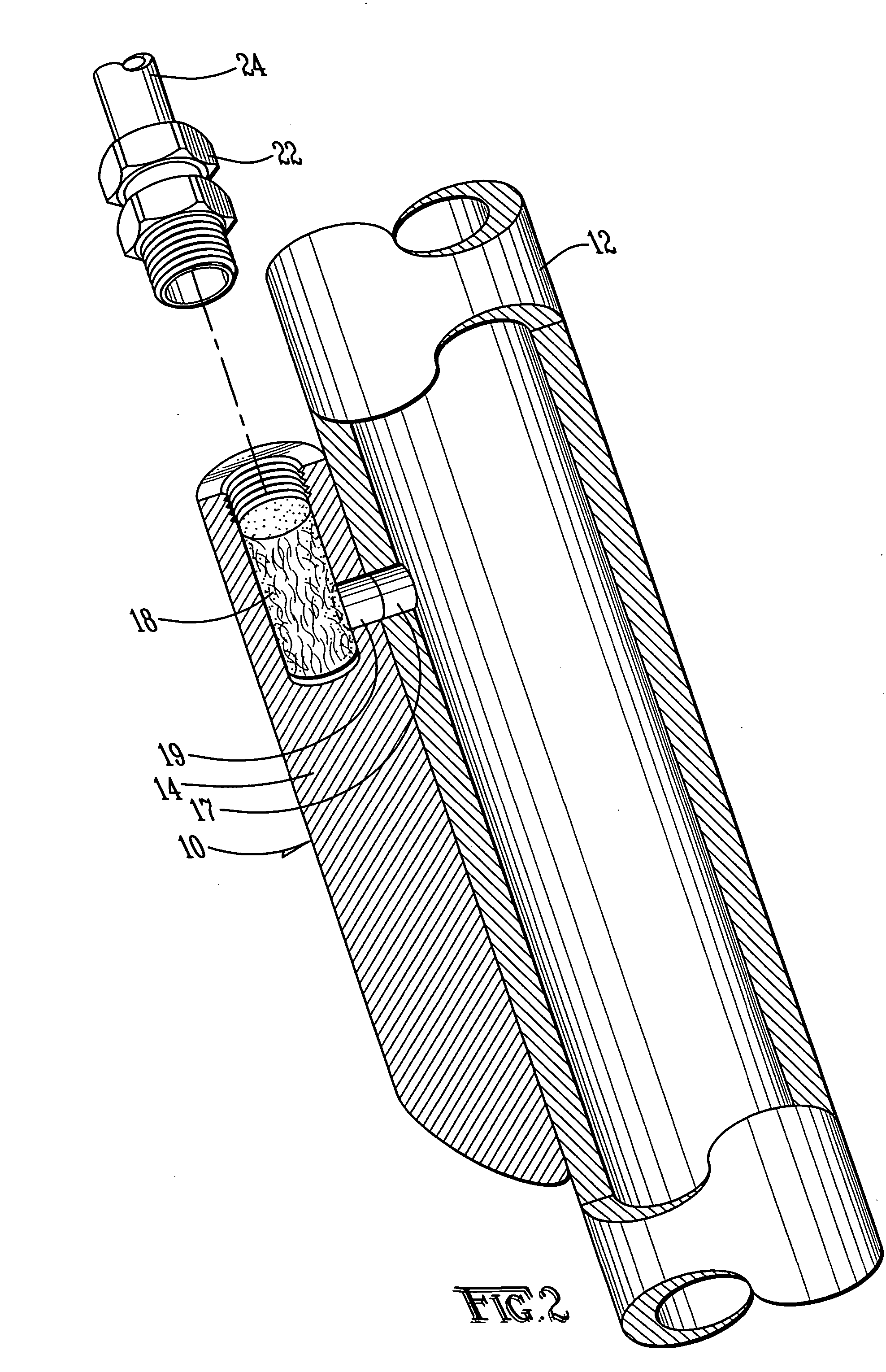
[0029] With reference to FIG. 1, downhole subassembly 10 of a preferred embodiment of the present invention may be described. Downhole subassembly 10 is preferably designed for deployment at or near the end of a production tube for placement in a well, just above the position for placement of the borehole packer. Downhole subassembly 10 is composed of production tube segment 12 and monitor tip 14. In the preferred embodiment, production tube segment 12 is a tube constructed of steel or other appropriately strong material, threaded to fit into other segments of the well production tube (shown in dotted lines in FIG. 1). In the preferred embodiments, production tube segment 10 is sized to fit either of the most common 2⅜ inch or 2⅞ inch production tube sizes used in CBM extraction. In alternative embodiments, other sizes may be accommodated. In the preferred embodiment, the hollow interior of production tube segment 12 is kept clear in order to minimize blockage and facilitate periodi...


PUM


Abstract

An apparatus for monitoring the pressure in a gas well at a downhole location is disclosed. The apparatus uses a capillary tube connecting a downhole monitoring assembly with a pressure gauge or gauges at the wellhead. The downhole monitoring assembly and capillary tube are located externally to the production tube so as not to block the production tube for cleaning or other uses. A passage from the interior of the production tube passes gas to the capillary tube in order to measure the pressure at the downhole end of the production tube.

Description

BACKGROUND OF THE INVENTION [0001] This application claims the benefit of U.S. provisional patent application No. 60 / 655,854, filed Feb. 23, 2005. [0002] The present invention relates to pressure monitoring systems for gas wells, and in particular to an apparatus for monitoring the pressure at the bottom of a gas well by means of a capillary tube external of the well's production tube. [0003] It has long been recognized that coalbeds often contain combustible gaseous hydrocarbons that are trapped within the coal seam. Methane, the major combustible component of natural gas, accounts for roughly 95% of these gaseous hydrocarbons. Coal beds may also contain smaller amounts of higher molecular weight gaseous hydrocarbons, such as ethane and propane. These gases attach to the porous surface of the coal at the molecular level, and are held in place by the hydrostatic pressure exerted by groundwater surrounding the coal bed. [0004] The methane trapped in a coalbed seam will desorb when th...

Claims


Application Information

Patent Timeline
IPC IPC(8): E21B47/06
CPCE21B47/06
Inventor CONRAD, GREG ALLEN
Owner CONRAD GREG ALLEN
Learn More