
Isolator using externally pressurized sealing bellows

Active Publication Date: 2006-08-17
HONEYWELL INT INC
View PDF22 Cites 14 Cited by
  • Summary
  • Abstract
  • Description
  • Claims
  • Application Information

AI Technical Summary

Benefits of technology

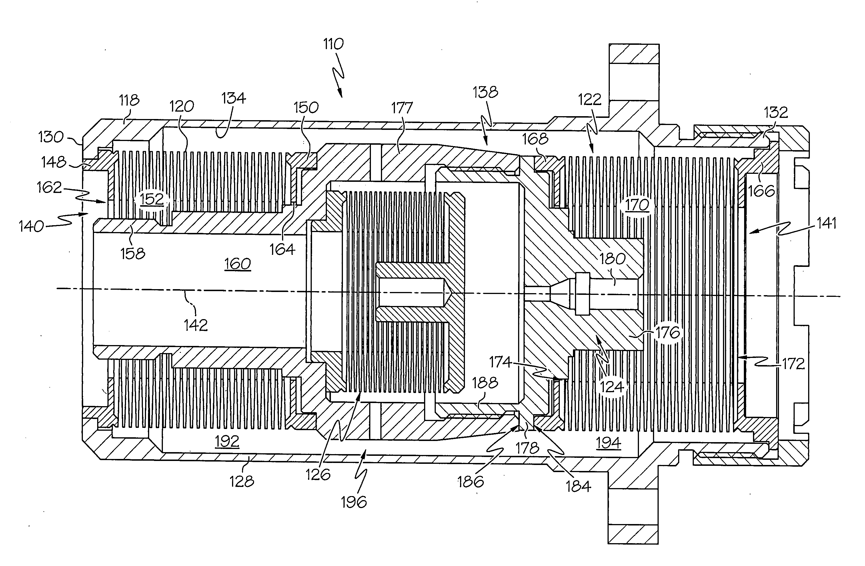
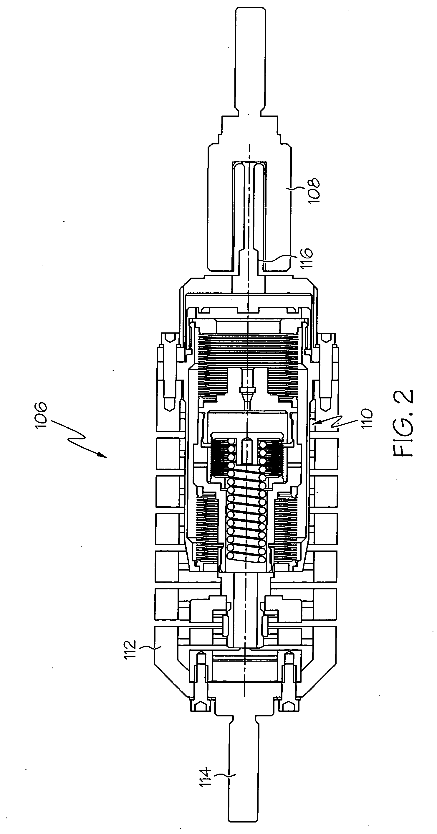
[0007] An apparatus is provided for vibration and damping and isolation. In one exemplary embodiment, the apparatus comprises a housing, a first bellows, a second bellows, a restrictive flow passage, fluid, and a piston. The housing has an inner surface defining a passage therethrough. The first bellows is disposed within the housing passage and has an outer surface spaced apart from the housing inner surface to define a first chamber having a volume. The second bellows is disposed within the housing passage and has an outer surface spaced apart from the housing inner surface to define a second chamber having a volume. The restrictive flow passage is in fluid communication with the first and second chambers. Fluid is disposed within the first chamber, the second chamber, and the restrictive flow passage. The piston is coupled to at least the second bellows and disposed at least partially within the restrictive flow passage. The piston is configured to selectively receive a force to thereby move the piston through the housing passage to increase the first chamber volume and decrease the second chamber volume or to decrease the first chamber volume and increase the second chamber volume.
[0008] In another exemplary embodiment, the apparatus includes a housing, a first bellows, a second bellows, a piston, and fluid. The housing has a first end, a second end, an inner surface, and a passage defined by the inner surface extending between the first and second ends. The first bellows is disposed within the housing passage and has a first end, a second end, and an outer surface. The first bellows first end is coupled to the housing first end, and the first bellows second end has a surface. The first bellows outer surface and housing inner surface define a first chamber having a volume. The second bellows is disposed within the housing passage and has a first end, a second end, an inner surface, and an outer surface. The second bellows first end is coupled to the housing second end, the second bellows inner surface defines a cavity therein, and the second bellows outer surface and housing inner surface defining a second chamber having a volume. The piston is disposed within the housing passage, and has a shaft having a first section, a second section and an outer surface. The shaft first section is at least partially disposed in the second bellows cavity, the shaft second section is at least partially disposed outside of the second bellows

Problems solved by technology

A precision pointing system carrying a sensor, such as a telescope as its payload, may be susceptible to disturbances that produce structural vibrations and, consequently, pointing errors.
For the most part, because these systems tend not to have significant, inherent damping, these structural vibrations may degrade system performance and even cause structural fatigue over time.
Although the D-STRUT® isolation strut operates effectively in most applications, it may not be appropriate to implement in other applications.
For example, in circumstances in which a space constraint includes the need for an elongated isolation strut, lengthening the first and second sealed bellows to accommodate such a space constraint may present certain drawbacks.
In particular, if one of the first and / or second sealed bellows is too long, it may experience column buckling when force is applied to the piston.
As a result, the amount of force applied to the piston may need to be decreased to avoid column buckling of either the first and / or second sealed bellows; thus, the isolation strut may not be able to damp vibration of relatively large payloads.
In such cases, complicated and more costly configurations are typically employed.

Method used


Image

  • Isolator using externally pressurized sealing bellows
  • Isolator using externally pressurized sealing bellows
  • Isolator using externally pressurized sealing bellows

Examples


Embodiment Construction

[0015] The following detailed description of the invention is merely exemplary in nature and is not intended to limit the invention or the application and uses of the invention. While the isolation struts are discussed with reference to exemplary embodiments, any one of numerous other embodiments of a fluid filled isolation strut may be implemented as well. Fluid, as used in the present invention, can be any viscous liquid or any gas known in the art. Furthermore, there is no intention to be bound by any theory presented in the preceding background of the invention or the following detailed description of the invention.

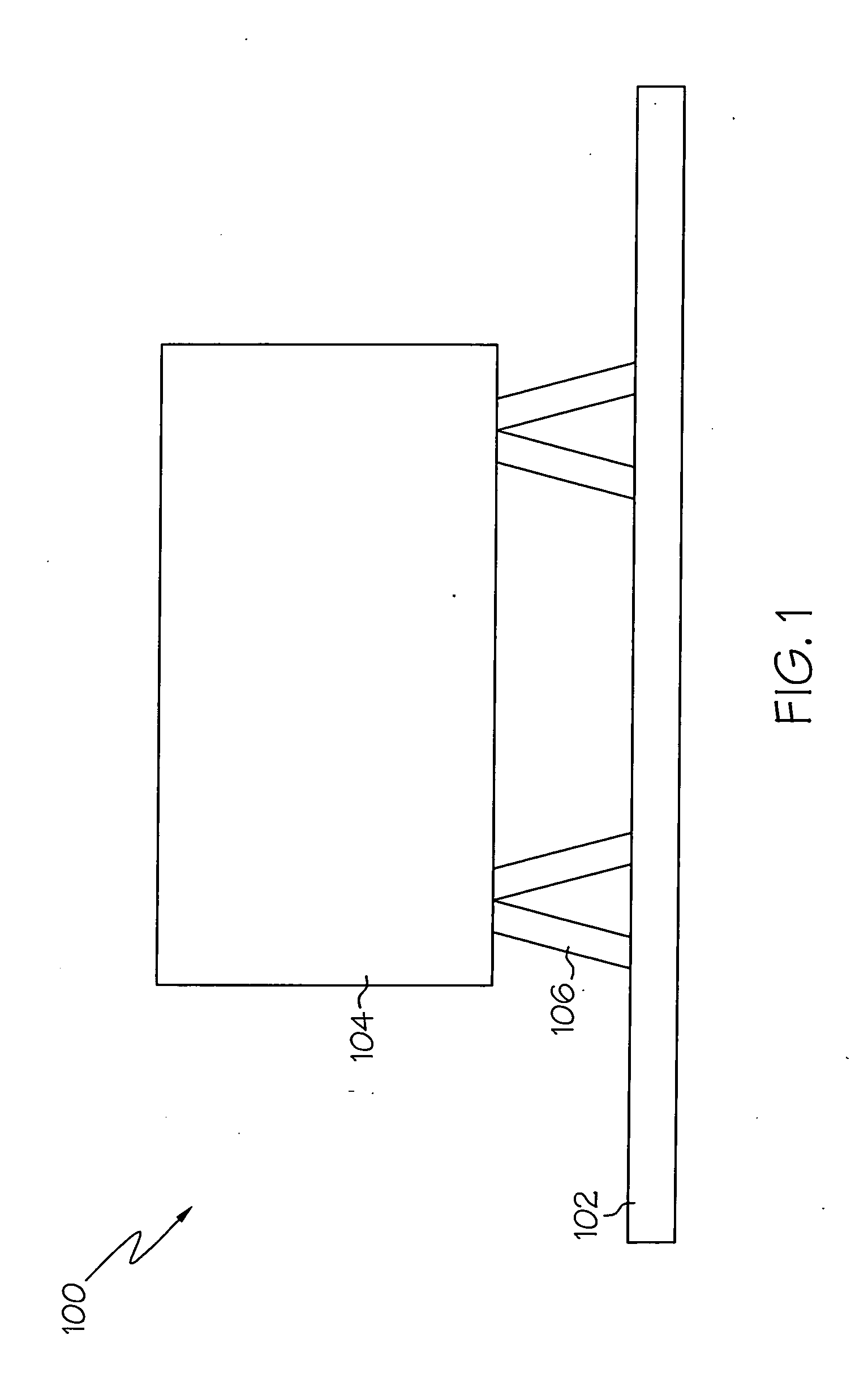
[0016]FIG. 1 illustrates an exemplary system having vibration damping and isolation. The system 100 may be implemented in any one of numerous environments, such as in space, terrestrially, or under water. The system 100 includes a base 102, a payload 104, and at least one vibration isolation apparatus 106. The base 102 is configured to provide a platform to which the...


PUM


Abstract

Apparatus are provided for a damping system. The system includes a housing having an inner surface defining a passage therethrough, a first bellows disposed within the passage, the first bellows having an outer surface and spaced apart from the housing inner surface to define a first chamber having a volume, a second bellows disposed within the passage, the second bellows having an outer surface and spaced apart from the housing inner surface to define a second chamber having a volume, a restrictive flow passage in fluid communication with the first and second chambers, fluid disposed within the first chamber, the second chamber, and the restrictive flow passage, and a piston coupled to the second bellows and disposed at least partially within the restrictive flow passage, the piston configured to selectively receive a force to thereby move the piston through the housing passage.

Description

FIELD OF THE INVENTION [0001] The present invention generally relates to vibration damping and isolation systems, and more particularly relates to isolators. BACKGROUND OF THE INVENTION [0002] A precision pointing system carrying a sensor, such as a telescope as its payload, may be susceptible to disturbances that produce structural vibrations and, consequently, pointing errors. Such vibrations may be attributed to mechanical components or assemblies, such as reaction wheel assemblies that are used as actuators in the precision pointing system. For the most part, because these systems tend not to have significant, inherent damping, these structural vibrations may degrade system performance and even cause structural fatigue over time. Therefore, an efficient means of providing damping and isolation to the system may be needed. [0003] Typically, to minimize performance degradation caused by vibrations, a passive-mass damping and isolation system is used for damping the structure and i...

Claims


Application Information

Patent Timeline
IPC IPC(8): F16F9/24
CPCF16F9/16F16F9/361
Inventor RUEBSAMEN, DALE T.BOYD, JAMES H.
Owner HONEYWELL INT INC
Learn More