
Hand pump for pumping fluid

a technology of hand-operated pumps and fluids, which is applied in the field of single-hand-operated mini-pumpers, can solve the problems of short breath, less effective sucking, and difficulty in sucking liquid, and achieve the effect of increasing the volume of the chamber

Inactive Publication Date: 2011-05-19
SOURCE VAGABOND SYST LTD
View PDF14 Cites 2 Cited by
  • Summary
  • Abstract
  • Description
  • Claims
  • Application Information

AI Technical Summary

Benefits of technology

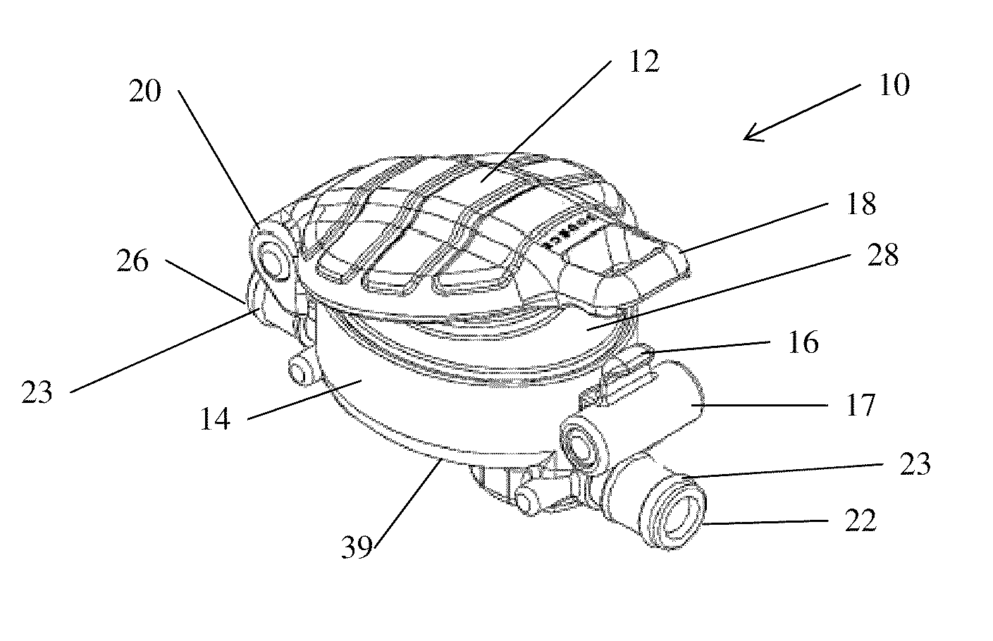
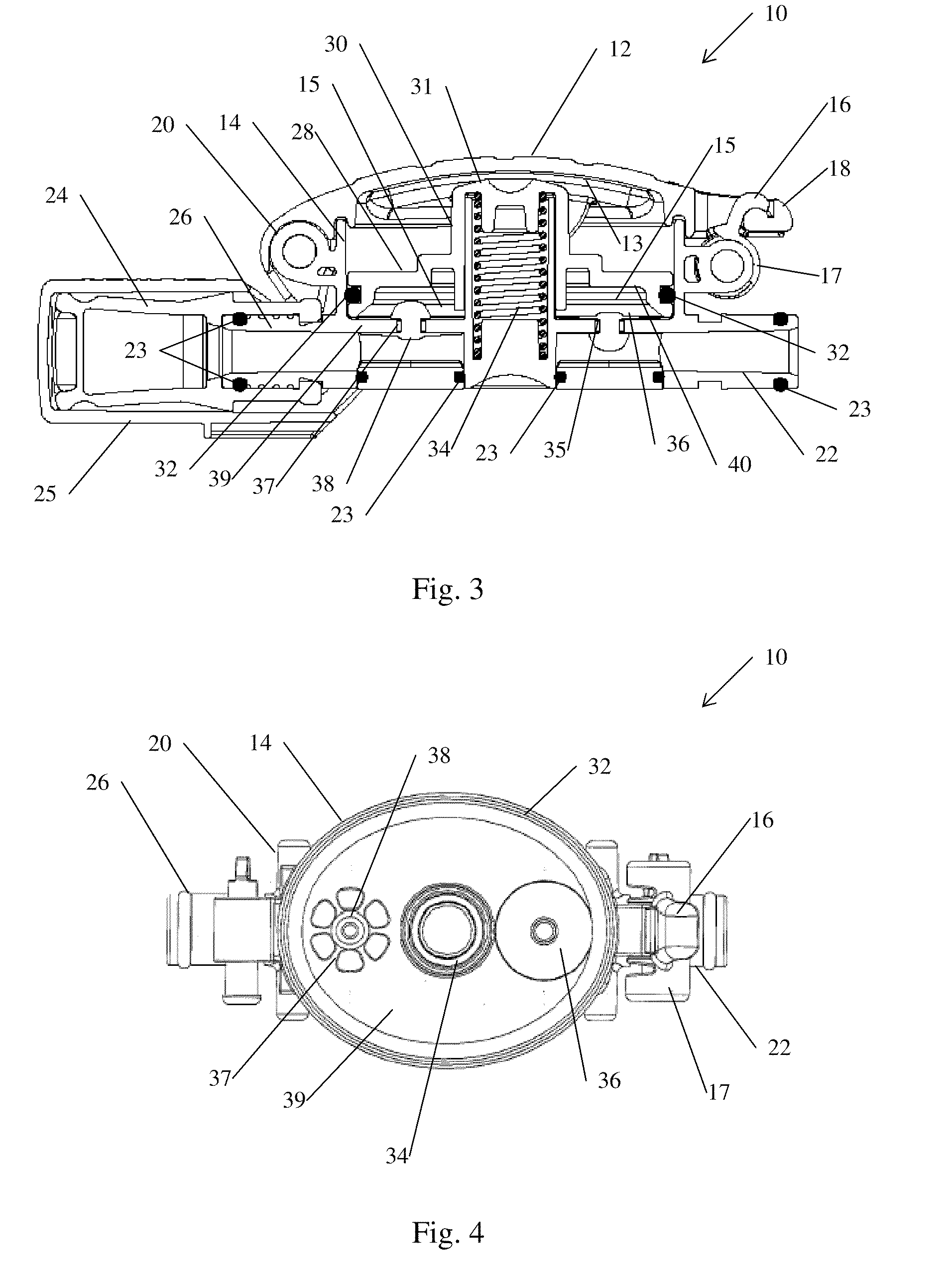
[0011]There is thus provided, in accordance with some embodiments of the present invention, a hand operable pump device for pumping fluids. The device includes a hollow body, with an inlet port and an outlet port, the inlet port provided with a one-way valve permitting fluid flow into the pump and the outlet port provided with a one-way valve permitting fluid flow out of the pump. The device further includes an oval piston designed to be pressed inwardly from an initial position by the hand, decreasing the volume of an oval chamber with a corresponding oval cross-section, the chamber being located within the pump and fluidically connected with the inlet and outlet ports, and to return to the initial position when released, increasing the volume of the chamber.

Problems solved by technology

Sucking the liquid requires an effort on the part of the user.
Another scenario is high altitude trekking were the user may be short of breath, and where decreased ambient pressure may make sucking less effective.
Another scenario that may render sucking ineffective is incorporation of an in-line filter into the hydration system.
For example, potable liquid may not be readily available for filling a hydration system.
In such a case, sucking may not provide a sufficient force to cause a liquid to flow through at an acceptable rate.
Therefore, many pumps that are known in the art cannot be conveniently operated with a single hand.
Operation of such pumps may, therefore, entail interrupting the user's activities until pumping is complete.
On the other hand, pumps have been described that may be conveniently powered with one hand, but cannot provide sufficient pumping force to cause an acceptable rate of liquid flow.

Method used


Image

  • Hand pump for pumping fluid
  • Hand pump for pumping fluid
  • Hand pump for pumping fluid

Examples


Embodiment Construction

[0031]In the following detailed description, numerous specific details are set forth in order to provide a thorough understanding of the invention. However, it will be understood by those of ordinary skill in the art that the invention may be practiced without these specific details. In other instances, well-known methods, procedures, components, modules, units and / or circuits have not been described in detail so as not to obscure the invention.

[0032]A hand pump in accordance with embodiments of the present invention is designed to pump a liquid at an acceptable rate while being operated by a single hand. The pump includes a hollow body enclosing a cylinder with an oval cross section. The cylinder is closed at one end. A piston with a corresponding oval shape is designed to slide back and forth along the axis of the cylinder, closing the open end of the cylinder. An oval shaped rubber ring forms a seal between the piston and the walls of the cylinder in the manner of an O-ring. Moti...


PUM


Abstract

A hand operable pump device for pumping fluids includes a hollow body and an oval piston. The hollow body includes an inlet port and an outlet port. The inlet port is provided with a one-way valve permitting fluid flow into the pump. The outlet port is provided with a one-way valve permitting fluid flow out of the pump. The oval piston is designed to be pressed inwardly from an initial position by the hand, decreasing the volume of an oval chamber with a corresponding oval cross-section. The chamber is located within the pump and is fluidically connected with the inlet and outlet ports. The oval piston is further designed to return to the initial position when released, increasing the volume of the chamber.

Description

FIELD OF THE INVENTION[0001]The present invention relates to pumps. More particularly, the present invention relates to a single hand operated mini pump for pumping fluid or air.BACKGROUND OF THE INVENTION[0002]Hydration systems are portable liquid container systems designed to enable a user engaged in an outdoor activity, for example, a sport, to instantly access the liquid and to drink as needed while on the move. For example, the user may prevent dehydration by drink at a sufficient rate and frequency to replacing body fluids lost through perspiration. By replacing body fluid loss at the required capacity, the user may avoid dehydration and continue to perform the activity at a desired level of performance.[0003]A typical hydration system is designed to operate with minimal use of the user's hands. For example, a hydration system may include a flexible bag or bladder made of a material impermeable to liquids. The flexible bag may be designed to be worn by the user, for example, b...

Claims


Application Information

Patent Timeline
Patent Type & Authority Applications(United States)
IPC IPC(8): F04B33/00
CPCF04B33/00A45F3/20
Inventor GILL, YORAM
Owner SOURCE VAGABOND SYST LTD
Learn More