Eureka AIR delivers breakthrough ideas for toughest innovation challenges, trusted by R&D personnel around the world.

Satellite information autonomous distribution satellite, satellite information collecting system, and satellite terrestrial test system

a satellite information and autonomous technology, applied in the field of satellite information autonomous distribution satellite, satellite information collection system and satellite terrestrial test system, can solve the problems of not being able to acquire sufficient attribute information, and not being able to dedu

Inactive Publication Date: 2006-08-10
NAT INST OF INFORMATION & COMM TECH
View PDF2 Cites 12 Cited by
  • Summary
  • Abstract
  • Description
  • Claims
  • Application Information

AI Technical Summary

Benefits of technology

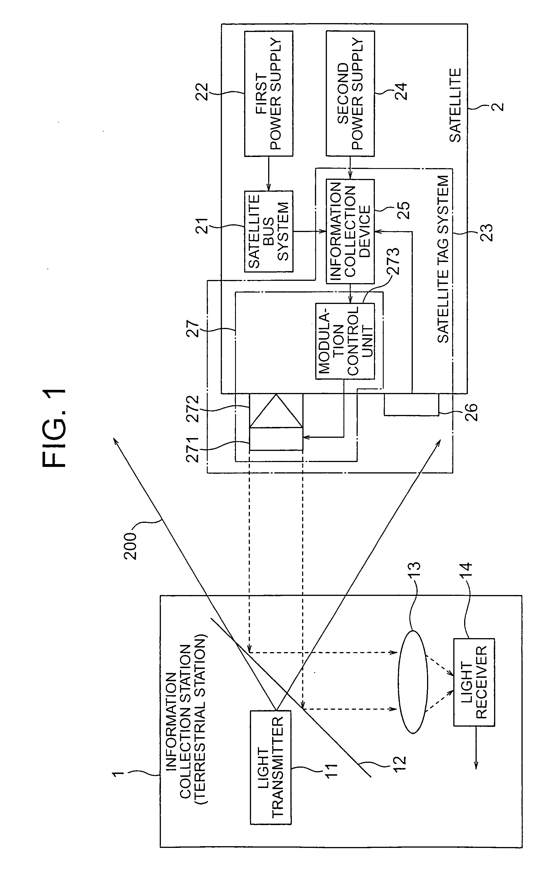
The present invention provides a satellite information autonomous distribution satellite and a satellite information collecting system that can collect and store attribute information for a satellite after a problem or malfunction has occurred. The satellite includes a reflecting type light modulating device that can transmit reflected light modulated by a modulation signal based on the attribute information. The system also includes a light transmitter and a light receiver for transmitting and receiving the modulated light. The invention allows for the collection of sufficient attribute information to analyze the causes of failure and restoration of the satellite's operation. It also allows for the identification of failures that may have occurred without being able to communicate with the satellite.

Problems solved by technology

However, in the event that something goes wrong with the satellite such as, for example, a problem such as it no longer being possible to use a transponder, etc., it is often not possible to acquire attribute information for the satellite using the directory command line.
It is not possible to acquire sufficient attribute information from before the occurrence of the problem of malfunction of the satellite because the communication speed of the directory command line is low.
In particular, because it is not possible to acquire sufficient attribute information for the conditions etc. up to the occurrence of the problem or malfunction, it is not possible to deduce the cause etc. of the malfunction of the satellite etc. in a fixed proportion of cases.
Further, there is little (or no) attribute information regarding specific problems for which it was originally thought that recovery was possible, so that recovery is not possible, or it may not be possible to cause the satellite to operate due to it being in an involuntary state (light load mode (LLM; Low Load Mode) states).
Further, after a satellite has been subjected to trouble or has malfunctioned, communication means for a satellite for which trouble has occurred so that transponders cannot be used or for malfunctioning satellites are cut, and attribute information for the satellite cannot be acquired using a directory command line.
It is therefore not possible to acquire attribute information thereafter, and it is therefore only possible to extrapolate the cause etc. of the problem etc. with the satellite, or it is not even possible to extrapolate the cause.
On the other hand, if the malfunctioning satellite is recovered, it is possible to reliably know the cause of the satellite malfunction but this tends to be prohibitively expensive.
This is therefore not appropriate for all satellites.
Further, it is not possible to recover satellites that are still operating in orbit even though they may be somewhat damaged.
Unfortunately, with this method it is necessary to annoyingly carry out the cabling every time a test takes place.
Further, the load here is substantial because it is necessary to provide a different cable connection section every satellite at test apparatus such as the vacuum chamber.

Method used


Image

  • Satellite information autonomous distribution satellite, satellite information collecting system, and satellite terrestrial test system
  • Satellite information autonomous distribution satellite, satellite information collecting system, and satellite terrestrial test system
  • Satellite information autonomous distribution satellite, satellite information collecting system, and satellite terrestrial test system

Examples


Embodiment Construction

[0026]FIG. 1 is a view showing the structure of a satellite information collection system of the present invention.

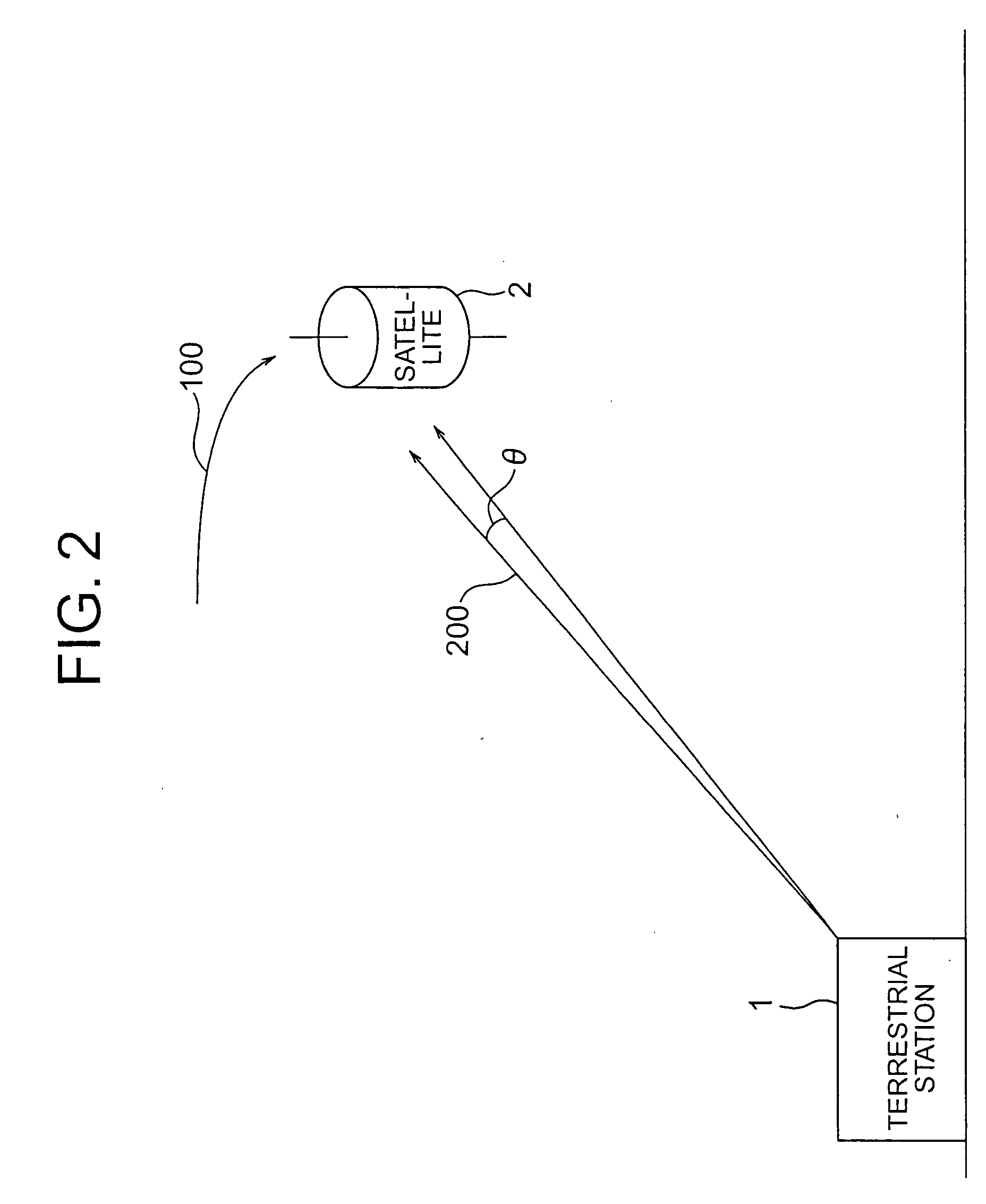
[0027]FIG. 2 is a view illustrating a satellite information collection system of the present invention.

[0028]FIG. 3 is a view illustrating a satellite information collection system of the present invention.

[0029]FIG. 4 is a view illustrating a satellite information collection system of the present invention.

[0030]FIG. 5 is a view illustrating a satellite information collection system of the present invention.

[0031]FIG. 6 is a view illustrating a further satellite information collection system of the present invention.

[0032]FIG. 7 is a view illustrating a further satellite information collection system of the present invention.

[0033]FIG. 8 is a view illustrating a further satellite information collection system of the present invention.

[0034]FIG. 9 is a view illustrating a further satellite information collection system of the present invention.

[0035]FIG. 10 is ...


PUM


Abstract

In order to provide a satellite information autonomous distribution satellite capable of collecting attribute information for satellites after failure or damage occurs at or to the satellite, an information collection device is operated by a second power supply provided independently from the first power supply operating the satellite bus system, is provided separately from the satellite bus system, and collects and stores attribute information. The light receiver is provided separately from the satellite bus system and forms a prescribed control signal when light sent from the information collection station is received. The reflecting type light modulating device is operated by the second power supply, is provided separately from the satellite bus system, and transmits reflected light superimposed with a modulation signal containing attribute information in the reflected waves using this modulation signal when a modulation signal is formed based on attribute information stored in the information collection device according to the shape of the control signal.

Description

CROSS-REFERENCE TO RELATED APPLICATIONS [0001] This application claims the conventional priority based on Japanese Application Serial No. 2004-259758, filed on Sep. 7, 2004, the disclosures of which are incorporated herein by reference. BACKGROUND OF THE INVENTION [0002] 1. Field of the Invention [0003] This invention relates to a satellite information autonomous distribution satellite, satellite information collection system and satellite terrestrial test system, and more particularly to a satellite information autonomous distribution satellite, satellite information collection system and satellite terrestrial test system capable of collecting satellite attribute information even after something goes wrong or hinders the satellite, or even in terrestrial testing prior to launching. [0004] 2. Description of the Related Art [0005] Communication between various satellites launched into orbit and terrestrial stations is usually carried out using electromagnetic waves. For example, it i...

Claims


Application Information

Patent Timeline
Patent Type & Authority Applications(United States)
IPC IPC(8): H04N7/20B64G1/66B64G7/00
CPCH04B7/18595
Inventor TOYOSHIMA, MORIOARIMOTO, YOSHINORI
Owner NAT INST OF INFORMATION & COMM TECH
Why Eureka
Eureka Blog
Learn More