Electronic device with main current limit circuit

a technology of current limit circuit and electronic device, which is applied in the direction of mobile unit charging station, transportation and packaging, and battery arrangement for several simultaneous batteries, etc., can solve the problems of rat's nest of wires, unsightly and difficult to conceal, and criss-crossing each other may resemble a tangled mess,

Inactive Publication Date: 2006-08-10
MOTOROLA INC
View PDF9 Cites 22 Cited by
  • Summary
  • Abstract
  • Description
  • Claims
  • Application Information

AI Technical Summary

Problems solved by technology

The problem with these “clusters” of devices is that they must all be interconnected with cables or wires.
While any one cable may appear thin and non-bulky, multiple cables, criss-crossing each other may resemble a tangled mess.
Often this “rat's nest” of wire can be unsightly and difficult to conceal.
Sometimes, for example, when they hang over the edge of a desk, a tangled bunch of wires may even constitute an obstacle over which one may trip.
However, for devices that may be coupled serially ad infinitum, a problem exists in that the serial chain may become so long that the power being drawn by the series combination overwhelms either the power source or the device's internal circuitry, which may include sensitive electronics, wiring or fuses.
In other words, while the wall outlet might be able to supply power to four or five devices coupled in series, coupling forty or fifty devices together may cause all kinds of power overload problems, including blown fuses and tripped circuit breakers.

Method used


Image

  • Electronic device with main current limit circuit
  • Electronic device with main current limit circuit
  • Electronic device with main current limit circuit

Examples


Embodiment Construction

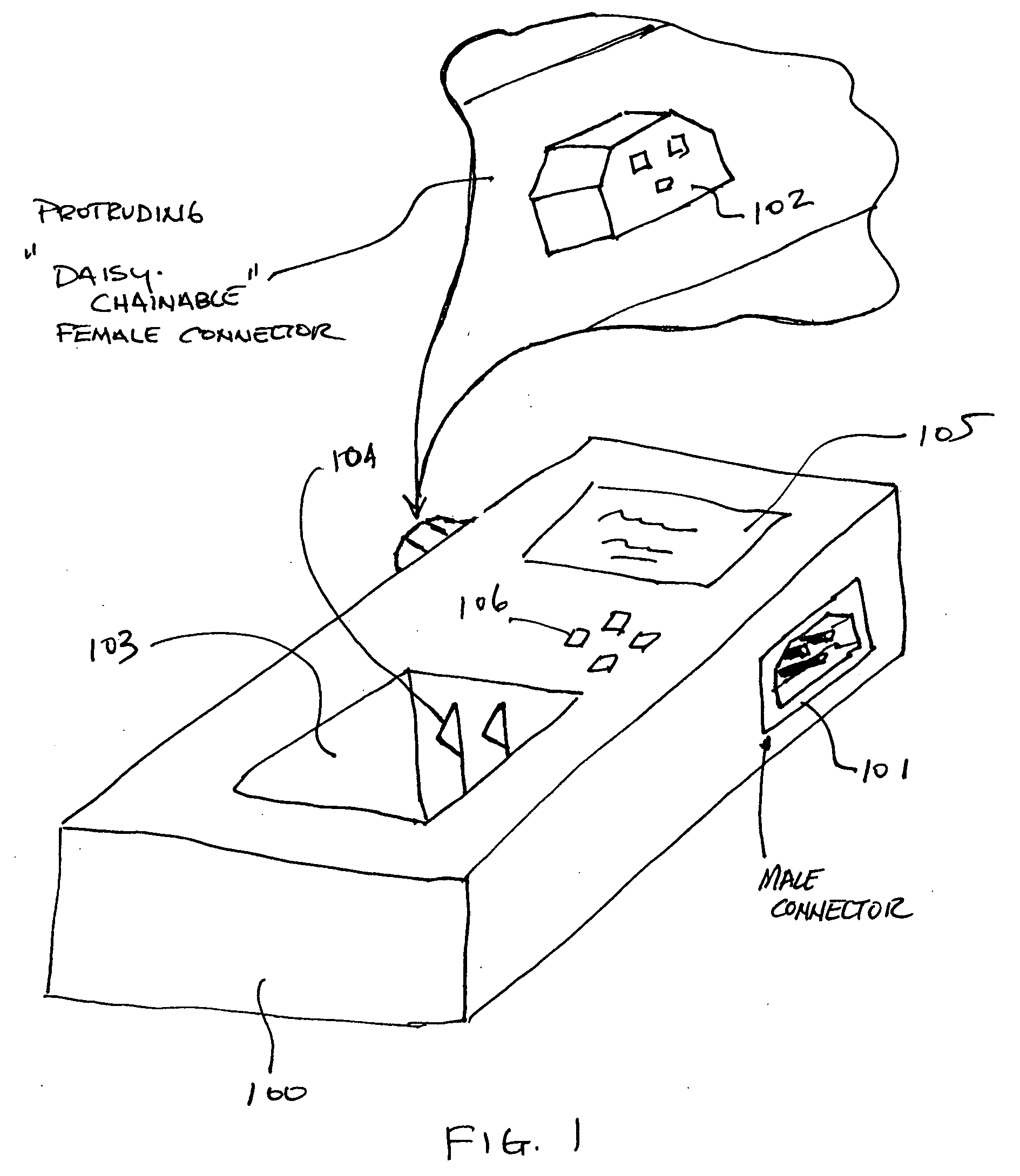
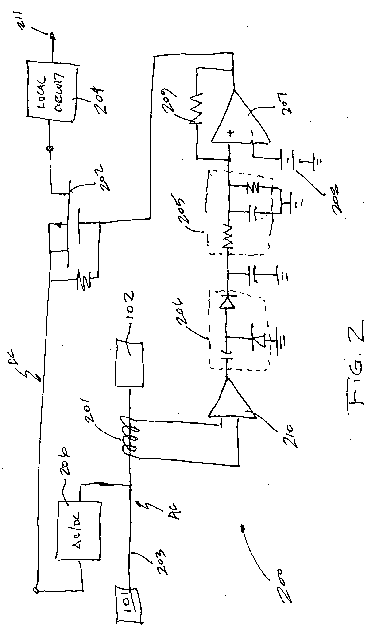
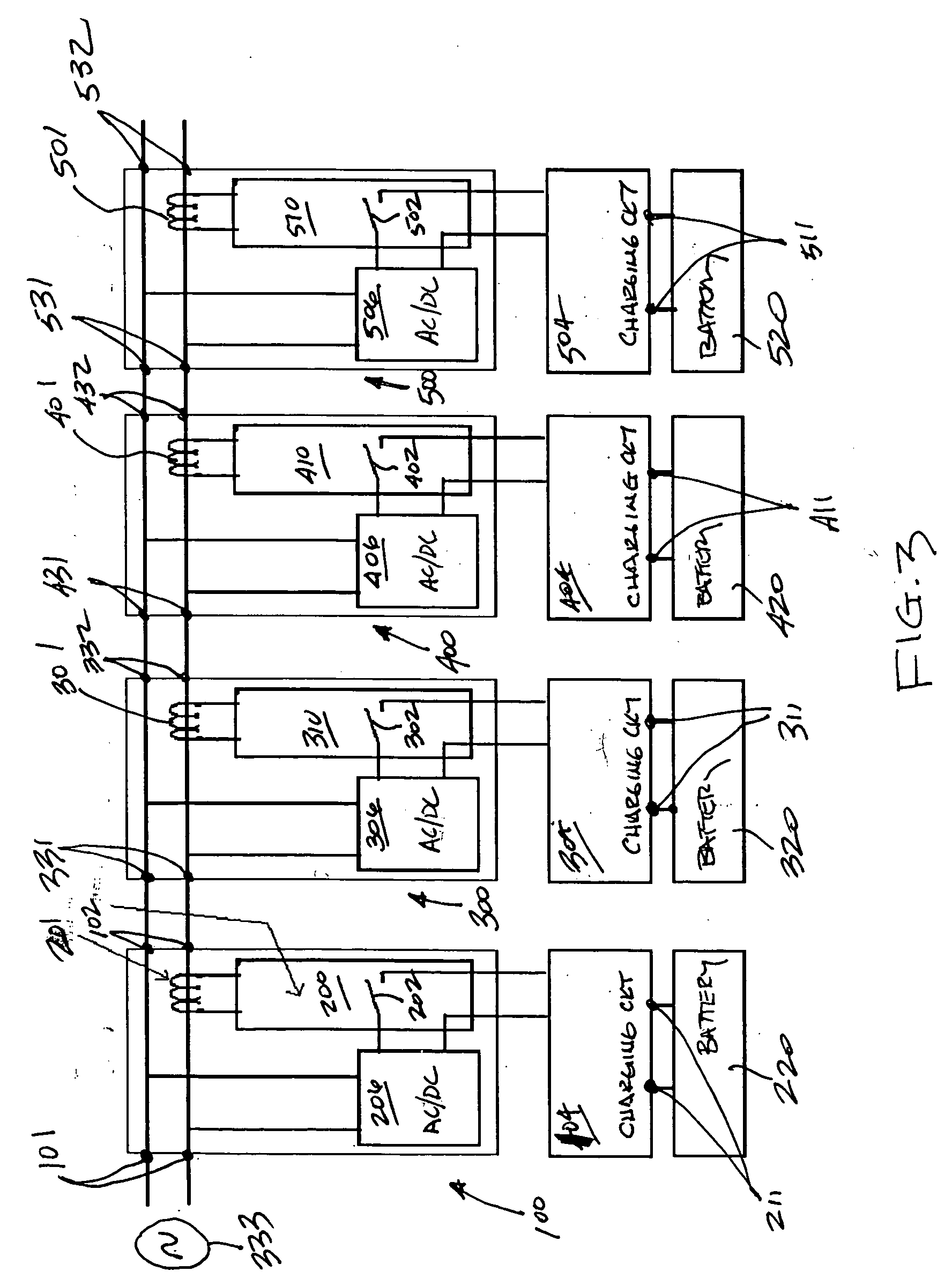
[0013] A preferred embodiment of the invention is now described in detail. Referring to the drawings, like numbers indicate like parts throughout the views. As used in the description herein and throughout the claims, the following terms take the meanings explicitly associated herein, unless the context clearly dictates otherwise: the meaning of “a,”“an,” and “the” includes plural reference, the meaning of “in” includes “in” and “on.”

[0014] This invention includes an electronic device, like a desktop battery charger for example, that may be coupled together serially with other similar devices. For example, one charger may be coupled to another identical charger, and so on, to form a multi-unit charger from a plurality of single unit chargers. This serial coupling, sometimes referred to as a “daisy chain configuration”, allows multiple devices, like chargers, to be coupled directly together in series without the need for unsightly cables.

[0015] In one preferred embodiment of the inv...


PUM


Abstract

This invention includes an electronic device that has both electrical contacts for coupling to local, application specific circuitry and contacts for supplying power to another electronic device. The electronic devices may be coupled in series, so as to eliminate the need for bulky, unsightly cables or wires. Since the devices may be coupled in series ad infinitum, the possibility exists that the series combination of devices may draw more power than either a power source can provide or sensitive internal circuitry, like fuses for example, can handle. As such, each electronic device includes a current limiting circuit having a current sense circuit and a switch coupled serially between the input and the output that powers the next electronic device. When the current drawn from the input to the output supplying power for the downstream devices exceeds a predetermined threshold, the switch deactivates the upstream chargers local circuitry. Once the downstream devices have completed their desired activities, the current drawn by the downstream devices will be reduced. When this occurs, the current sense circuits of the upstream devices will detect that the total current drawn has fallen below the predetermined threshold and will once again reactivate their local circuitry. In one embodiment, the electronic devices are desktop battery chargers. By disabling upstream battery chargers while downstream battery chargers complete their charging cycle, the current limiting devices in the upstream battery chargers ensure that fuses disposed within the upstream battery chargers do not blow. A blown fuse in an upstream charger could result in the entire series combination losing power. By including the current limiting circuit of the invention, a user may couple as many series devices together as they want without fear of blowing fuses in the upstream devices.

Description

BACKGROUND [0001] 1. Technical Field [0002] This invention relates generally to an electronic device having current limiting circuitry, and more specifically to an electronic device that is capable of supplying power to both local circuitry and a plurality second device, the electronic device having a current limit circuit that disables the local circuitry when the current drawn by the plurality of devices exceeds a predetermined threshold. [0003] 2. Background Art [0004] In modern day life, clusters of electronic devices are everywhere. For example, in the family living room, the entertainment system may consist of many devices linked together with wires and cables. A television may be connected to a variety of devices, including a VCR, a DVD player, a TiVo® system, a surround sound system, amplifiers and speakers. By connecting this variety of devices together, one may use the collective assembly of devices for hours and hours of entertainment. [0005] Similarly, in the office, mul...

Claims


Application Information

Patent Timeline
Patent Type & Authority Applications(United States)
IPC IPC(8): H02J7/00
CPCH02J7/0027H02J7/0045H02J7/0013H02J2310/22H02J7/0042
Inventor KRAUSE, JAMES O.
Owner MOTOROLA INC
Why Eureka
Try Eureka