
Method of controlling continuously variable transmission and control system

a technology of oil pressure control and transmission, applied in the direction of gearing control, gearing element control, belt/chain/gearing, etc., can solve the problems of increasing cost, affecting the accuracy of oil pressure control, and affecting the operation so as to improve the control accuracy of line pressure, ensure the accuracy of oil pressure control, and eliminate the effect of oil pressure control accuracy degradation

Inactive Publication Date: 2006-08-03
FUJITSU GENERAL LTD
View PDF12 Cites 91 Cited by
  • Summary
  • Abstract
  • Description
  • Claims
  • Application Information

AI Technical Summary

Benefits of technology

[0016] In this case, it is necessary to provide separate actuators for the line pressure control and the belt clamping pressure control, respectively, which leads to an increase in the cost. However, the enhancement of fuel economy contributes to an increase the commercial value of an automotive vehicle on which the oil pressure control system is installed, and a decrease in the costs of component parts of the whole vehicle is attained. Therefore, it is possible to obtain more advantageous effects than the cost cancellation.
[0017] In the above-mentioned oil pressure control system for the continuously variable transmission, it is necessary to accurately control oil pressure for use in control of the continuously variable transmission over the entire oil pressure range. More specifically, for example, structures, such as the springs, spools, and orifices of oil pressure valves, which form the oil pressure control system, have variations in size, shape, and so forth, generated during manufacturing thereof. Also, when a solenoid valve, such as a linear solenoid, is used as an actuator for actuating the oil pressure valve, the solenoid value has variations in electric characteristic. If the control amount of the oil pressure actuator is set, based on theoretical design values, without considering these variations, it is impossible to assure the accuracy of the oil pressure control.
[0018] Therefore, to control the oil pressure for use in controlling the continuously variable transmission over the entire oil pressure range with accuracy, a method of learning oil pressure has been proposed, which, however, is for the oil pressure control system for controlling line pressure and belt clamping pressure by a common oil pressure actuator (see e.g. Japanese Unexamined Patent Publication No. 2001-330117).
[0019] In this learning method, the current belt clamping pressure (hereinafter referred to as “the actual belt clamping pressure”) POUT(real) is measured by an oil pressure sensor disposed in a chamber of the secondary pulley. Learning correction of a belt clamping pressure command value POUT(tgt) is executed in advance to enable the control to be executed in a feedforward manner such that the difference between the belt clamping pressure command value POUT(tgt) outputted by an electronic control unit and the actual belt clamping pressure POUT(real) is reduced to zero.
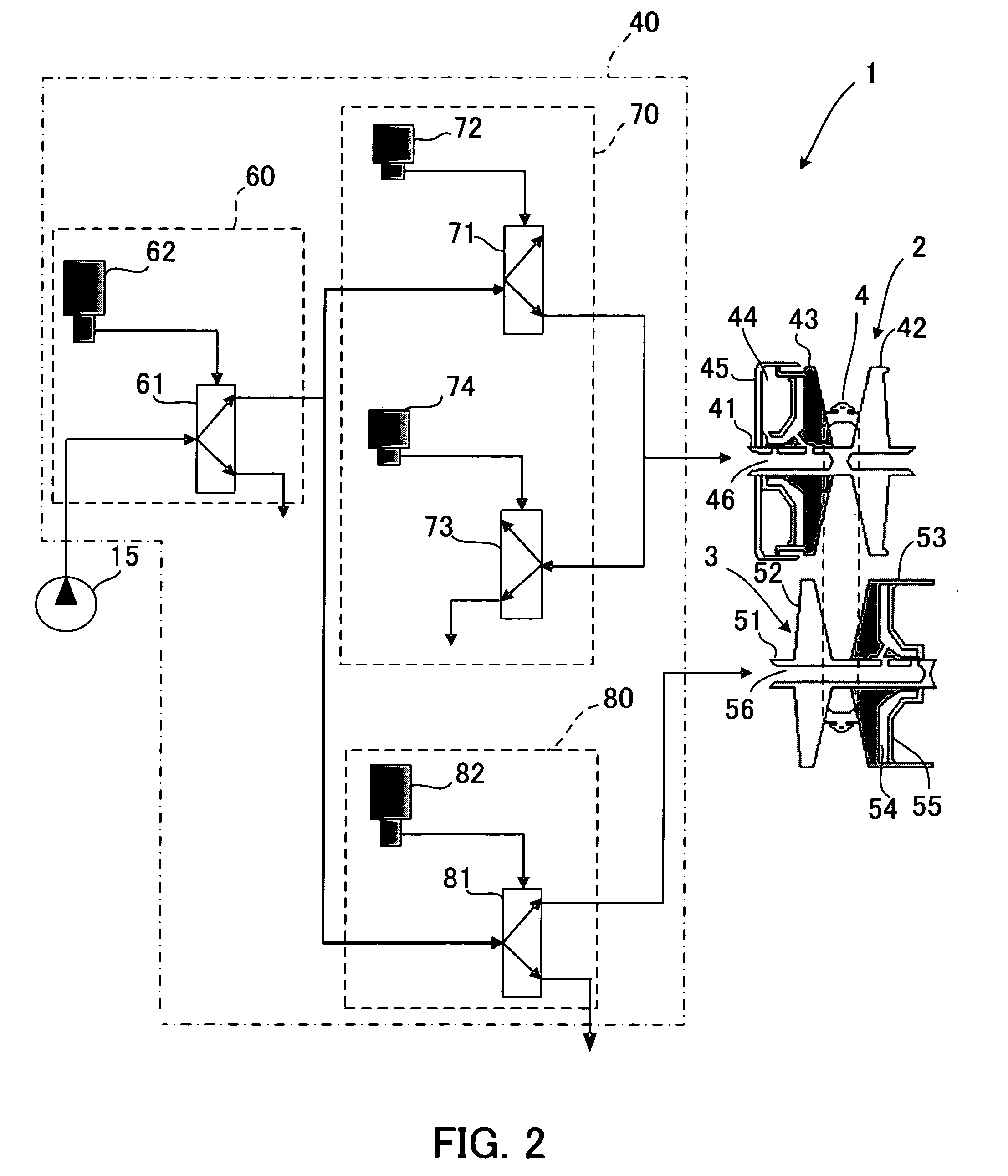
[0020] According to the above learning method, even if the springs, spools, and orifices of the oil pressure valves for controlling belt clamping pressure have variations in size, shape, and so forth, generated during manufacturing thereof, or even if a solenoid valve for actuating the oil pressure valve has variations in electric characteristic, it is possible to eliminate degradation of oil pressure control accuracy of a belt clamping pressure control section to thereby control the oil pressure over the entire oil pressure range with accuracy. As a result, the control accuracy of the line pressure is enhanced, and the electronic control unit can accurately estimate the line pressure and the belt clamping pressure based on an output value of the linear solenoid and a measured value of the belt clamping pressure by the oil pressure sensor.
[0021] However, the above learning method is assumed to be applied to the oil pressure control system that controls the oil pressure valve for generating line pressure and the oil pressure valve for generating belt clamping pressure by the common oil pressure actuator. Therefore, if the learning method is applied to a recent oil pressure control system that controls line pressure and belt clamping pressure by separate oil pressure actuators independently of each other, the control accuracy of the belt clamping pressure is enhanced but that of the line pressure is not, since learning correction of the line pressure is not executed. The line pressure serves as source pressure also for oil pressures for use in controlling devices other than the oil pressure control system of the continuously variable transmission, such as transmission control and clutch control, and hence to accurately control the devices and the continuously variable transmission, it is necessary to control the line pressure with accuracy. Further, the electronic control unit as well is required to accurately calculate and predict the actual line pressure. SUMMARY OF THE INVENTION

Problems solved by technology

This results in degradation of energy efficiency and fuel economy.
In this case, it is necessary to provide separate actuators for the line pressure control and the belt clamping pressure control, respectively, which leads to an increase in the cost.
If the control amount of the oil pressure actuator is set, based on theoretical design values, without considering these variations, it is impossible to assure the accuracy of the oil pressure control.

Method used


Image

  • Method of controlling continuously variable transmission and control system
  • Method of controlling continuously variable transmission and control system
  • Method of controlling continuously variable transmission and control system

Examples


Embodiment Construction

[0038] The invention will now be described in detail with reference to drawings showing a preferred embodiment thereof.

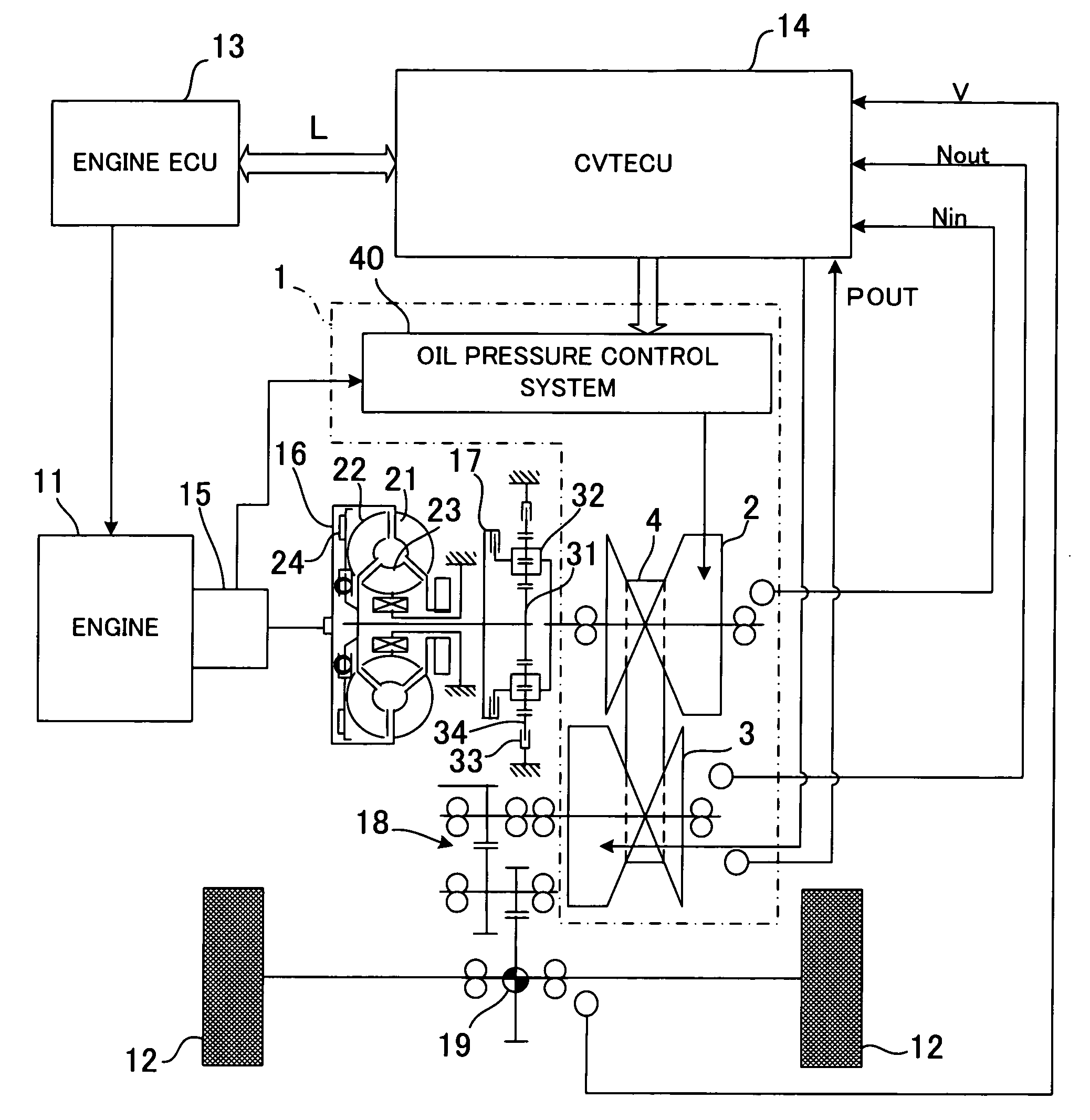
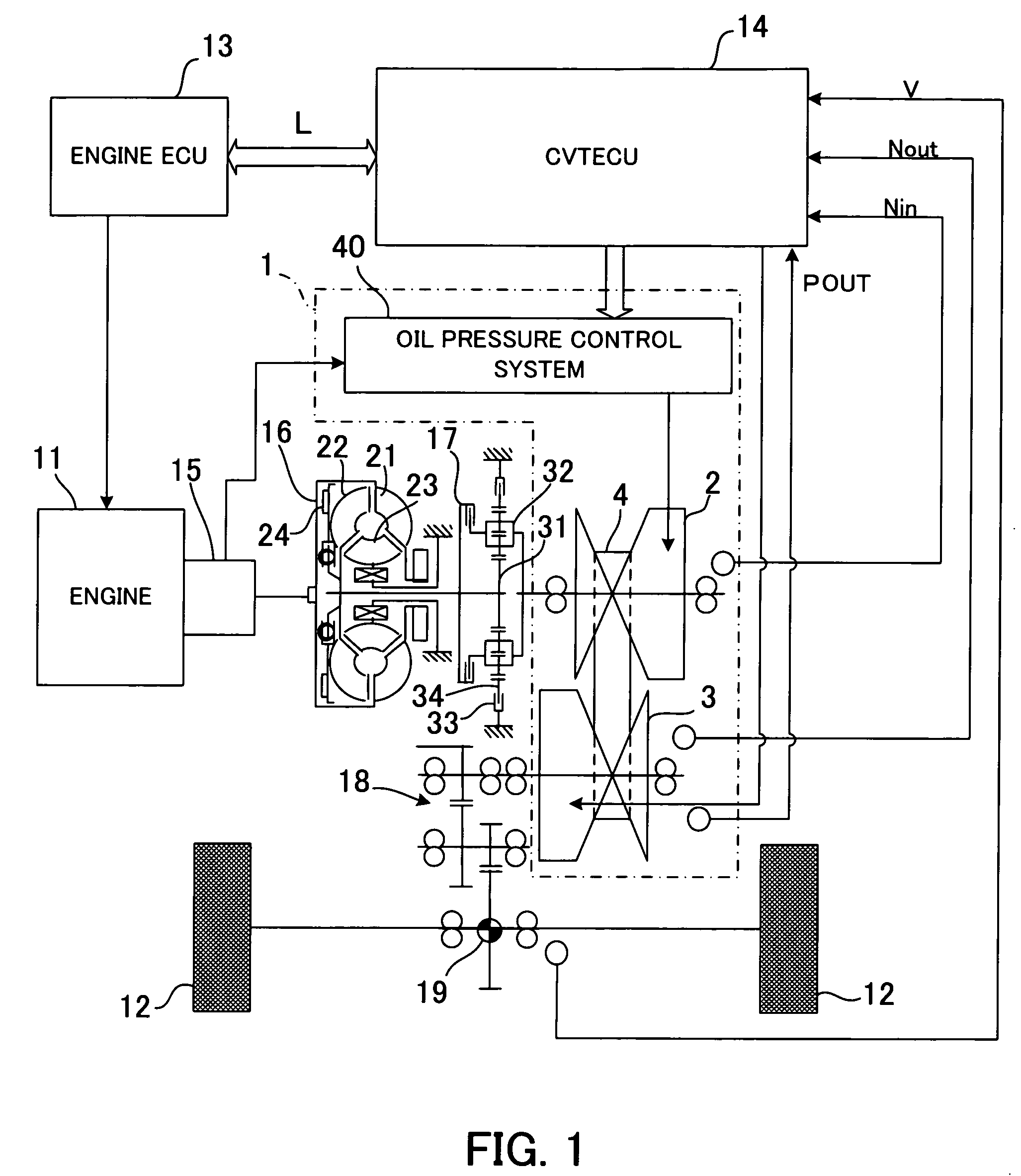
[0039] In the present embodiment, a method of controlling a continuously variable transmission according to the present invention is applied to a vehicle control system. FIG. 1 is a diagram showing a system configuration of the vehicle control system including a continuously variable transmission according to the present embodiment.

[0040] In the vehicle control system, a continuously variable transmission 1 of a belt type is disposed between an engine 11, which is a drive source of a vehicle, and drive wheels 12, and controlled objects are controlled by respective electronic control units (hereinafter simply referred to as “the ECUs”). More specifically, engine control is performed by an ECU 13 provided for the engine (hereinafter referred to as “the engine ECU 13”), and transmission control, described hereinafter, is performed by an ECU 14 provided for the contin...


PUM


Abstract

An oil pressure-learning method which enables an oil pressure control system that controls line pressure and belt clamping pressure by oil pressure actuators independently of each other, to accurately control both the line pressure and the belt clamping pressure. The oil pressure-learning method is applied to an oil pressure control system provided with a line pressure control solenoid for controlling a line pressure control valve, and a belt clamping pressure control solenoid for controlling a belt clamping pressure control valve. A belt clamping pressure command value that is outputted to the belt clamping pressure control solenoid as a control command value of belt clamping pressure, and a line pressure command value that is outputted to the line pressure control solenoid as a control command value of line pressure are learned in advance. This enables the oil pressure control system to control both the line pressure and the belt clamping pressure with accuracy.

Description

CROSS-REFERENCE TO RELATED APPLICATIONS [0001] This application is based on, and claims priority to, Japanese Application No. 2005-009723, filed Jan. 18, 2005, in Japan, and which is incorporated herein by reference.BACKGROUND OF THE INVENTION [0002] 1. Field of the Invention [0003] This invention relates to an oil pressure control method and an oil pressure control system, for a continuously variable transmission, and more particularly to an oil pressure control method and an oil pressure control system which are capable of controlling belt clamping pressure and line pressure as source pressure of the belt clamping pressure, of a belt-type continuously variable transmission, independently of each other. [0004] 2. Description of the Related Art [0005] Conventionally, a continuously variable transmission (also referred to as a “CVT”) is widely employed as an automatic transmission for automotive vehicles and the like, due to excellent robustness thereof. A belt-type continuously vari...

Claims


Application Information

Patent Timeline
Patent Type & Authority Applications(United States)
IPC IPC(8): F16H61/00F16H59/00
CPCF16H61/0021F16H61/66272F16H2061/0087F16H61/66
Inventor ISHIO, MASATO
Owner FUJITSU GENERAL LTD
Learn More