Circuit board fastening structure
a technology of circuit boards and fastening parts, applied in the direction of electrical apparatus casings/cabinets/drawers, instruments, computing, etc., can solve the problem of most time-consuming assembly
- Summary
- Abstract
- Description
- Claims
- Application Information
AI Technical Summary
Benefits of technology
Problems solved by technology
Method used
Image
Examples
Embodiment Construction
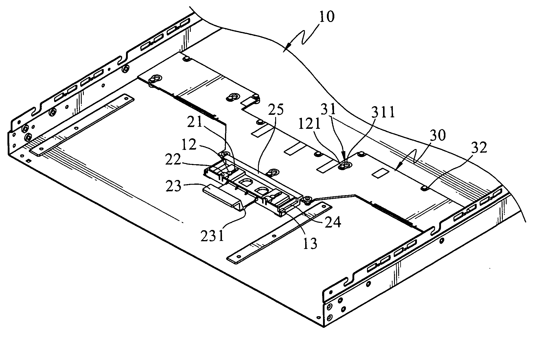
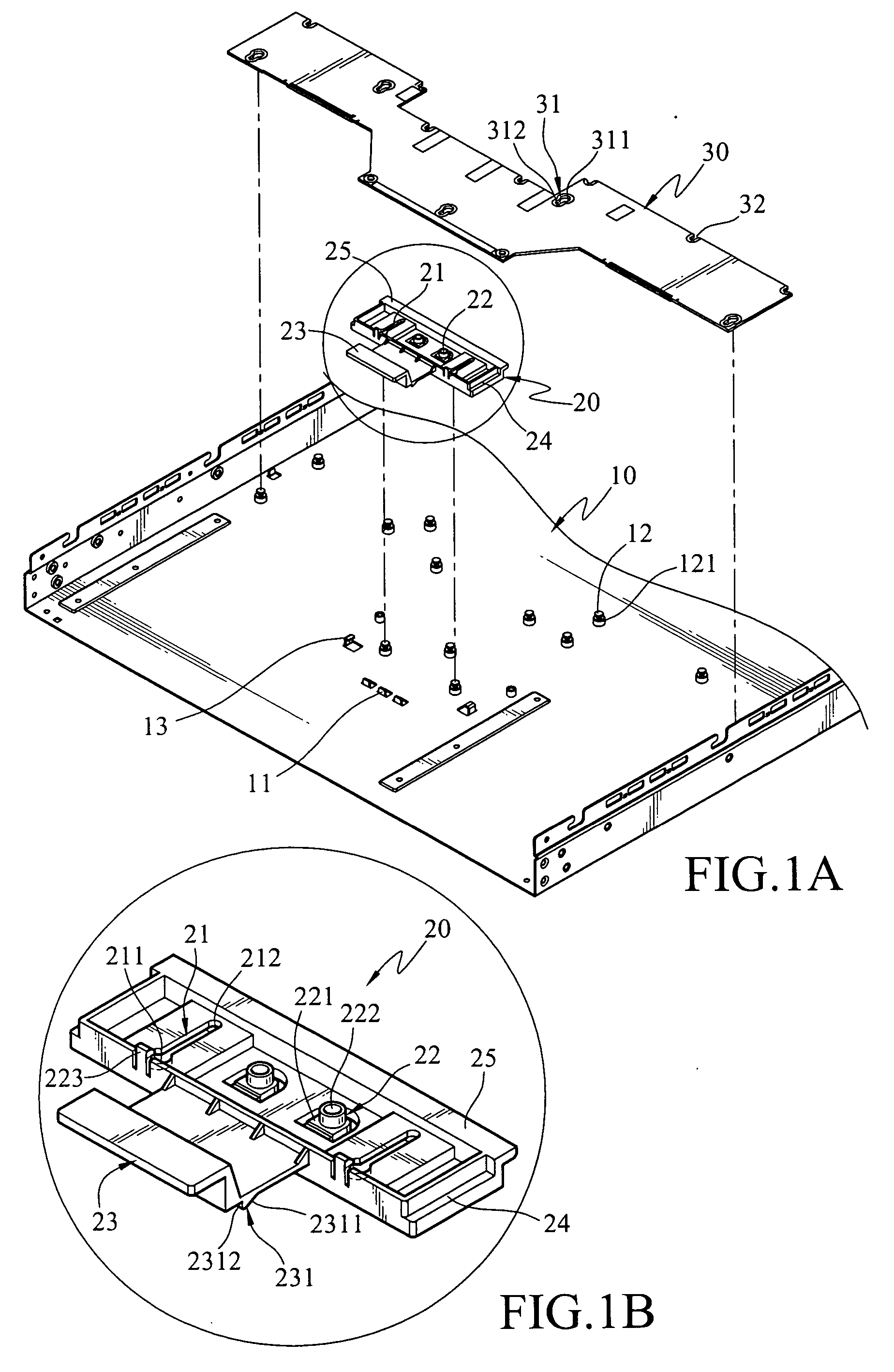
[0014] Referring to FIGS. 1A, 1B and 2, the circuit board fastening structure according to the invention includes a seat 10, a fastening plate 20 and a circuit board 30.
[0015] The seat 10 has a jutting detent wall 11, a plurality of anchoring members 12 and guiding tracks 13. The detent wall 11 is formed by a stamping method. Each of the anchoring members 12 has a groove 121 formed at a length at least equal to the thickness of the fastening plate 20 or the circuit board 30. The guiding tracks 13 are formed by a stamping method and opposite to each other for corresponding to two opposite sides of the fastening plate 20.
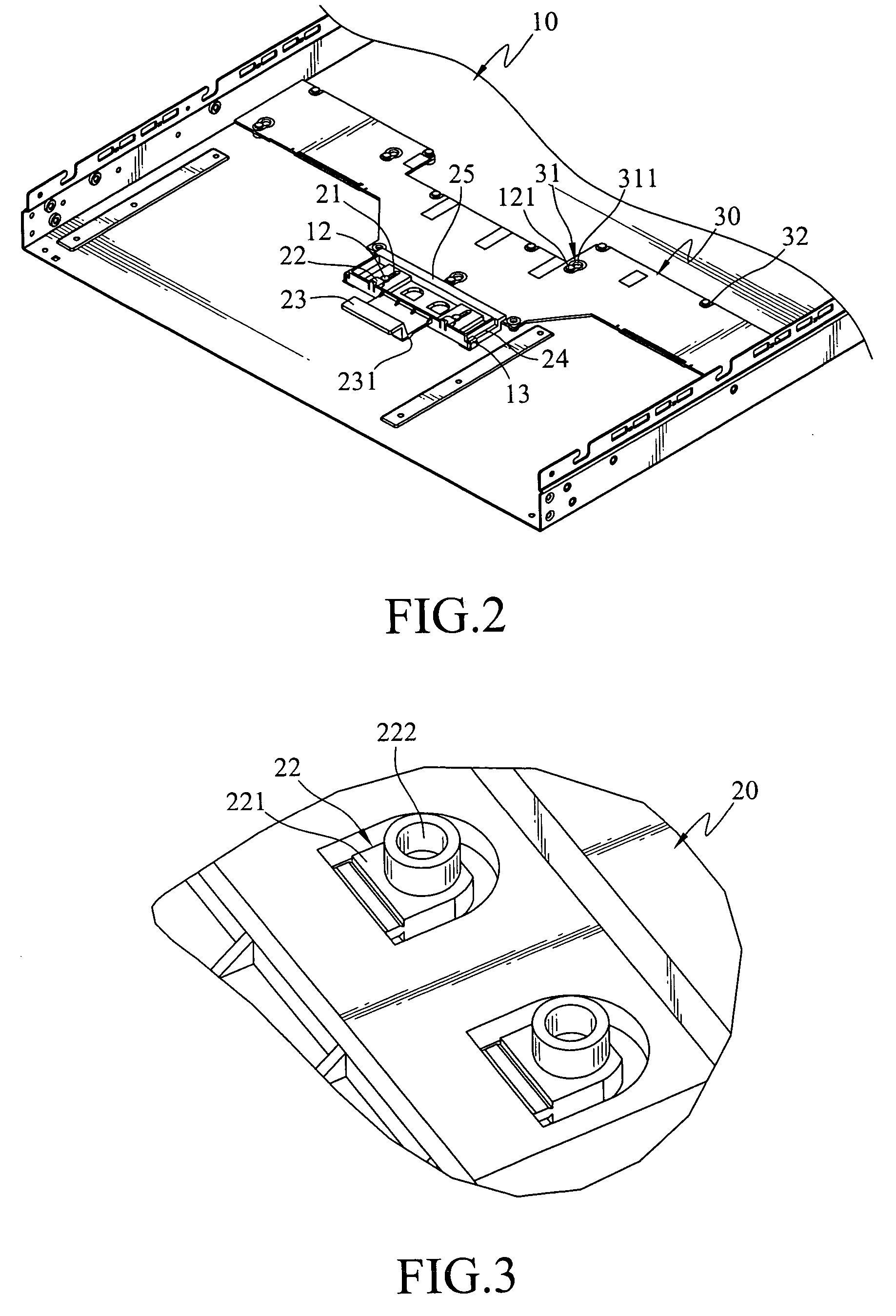
[0016] The fastening plate 20 is made of plastic. It has a plurality of gourd-shaped slots 21 and a flexible detent portion 22, a push portion 23, guiding channels 24 and a buffer member 25 (referring to FIG. 3 for the flexible detent portion).
[0017] Each of the gourd-shaped slots 21 includes an aperture 211 and a slit 212. The aperture 211 has a diameter greater t...
PUM
 Abstract
Description
Claims
Application Information
 - R&D
- Intellectual Property
- Life Sciences
- Materials
- Tech Scout
- Unparalleled Data Quality
- Higher Quality Content
- 60% Fewer Hallucinations
Browse by: Latest US Patents, China's latest patents, Technical Efficacy Thesaurus, Application Domain, Technology Topic, Popular Technical Reports.
© 2025 PatSnap. All rights reserved.Legal|Privacy policy|Modern Slavery Act Transparency Statement|Sitemap|About US| Contact US: help@patsnap.com


