Wireless multi-camera surveillance system

a multi-camera, wireless technology, applied in the field of surveillance systems, can solve the problems of inability to use, low cost, and inability to meet the needs of home owners, and achieve the effects of limiting the acceptance and use of home owners, and affecting the use of the system

Inactive Publication Date: 2006-08-03
X 10
View PDF2 Cites 11 Cited by
  • Summary
  • Abstract
  • Description
  • Claims
  • Application Information

AI Technical Summary

Benefits of technology

[0009] It is accordingly an object of the present invention to provide an improved multi-camera home surveillance system in which only one of the multiple cameras in the system is able to send an image at any given time to a central receiver, which overcomes the limitations and potential problems associated with the prior art systems of this type.
[0010] It is a further object of the present invention to provide an improved home surveillance system of the type described that reliably allows images from any selected one of a plurality of spaced locations in and around the home to be viewed at a single viewing station.
[0011] It is another object of the present invention to provide a home surveillance system of the type described in which the user has greater flexibility in positioning the video cameras and in which the system may receive its operating voltages from a simplified power supply such as a battery.

Problems solved by technology

Otherwise the television receiver would receive images from two or more cameras which are on at the same time, which would result in an unusable, garbled image.
This system is, however, relatively high in cost, which has thus far limited its acceptance and use by home owners.
Moreover, since this patented system makes use of the home ac power line to transmit the binary-coded control signals to the control modules to turn the cameras on and off, there may be occasions in which these control signals do not get to the control modules because of possible power line limitations such as noise, phase coupling issues, and the like.
Further the connection of control modules to the ac power line in this prior system limits the user's flexibility in selecting locations in the home at which the video cameras may be placed.

Method used


Image

  • Wireless multi-camera surveillance system
  • Wireless multi-camera surveillance system
  • Wireless multi-camera surveillance system

Examples


Embodiment Construction

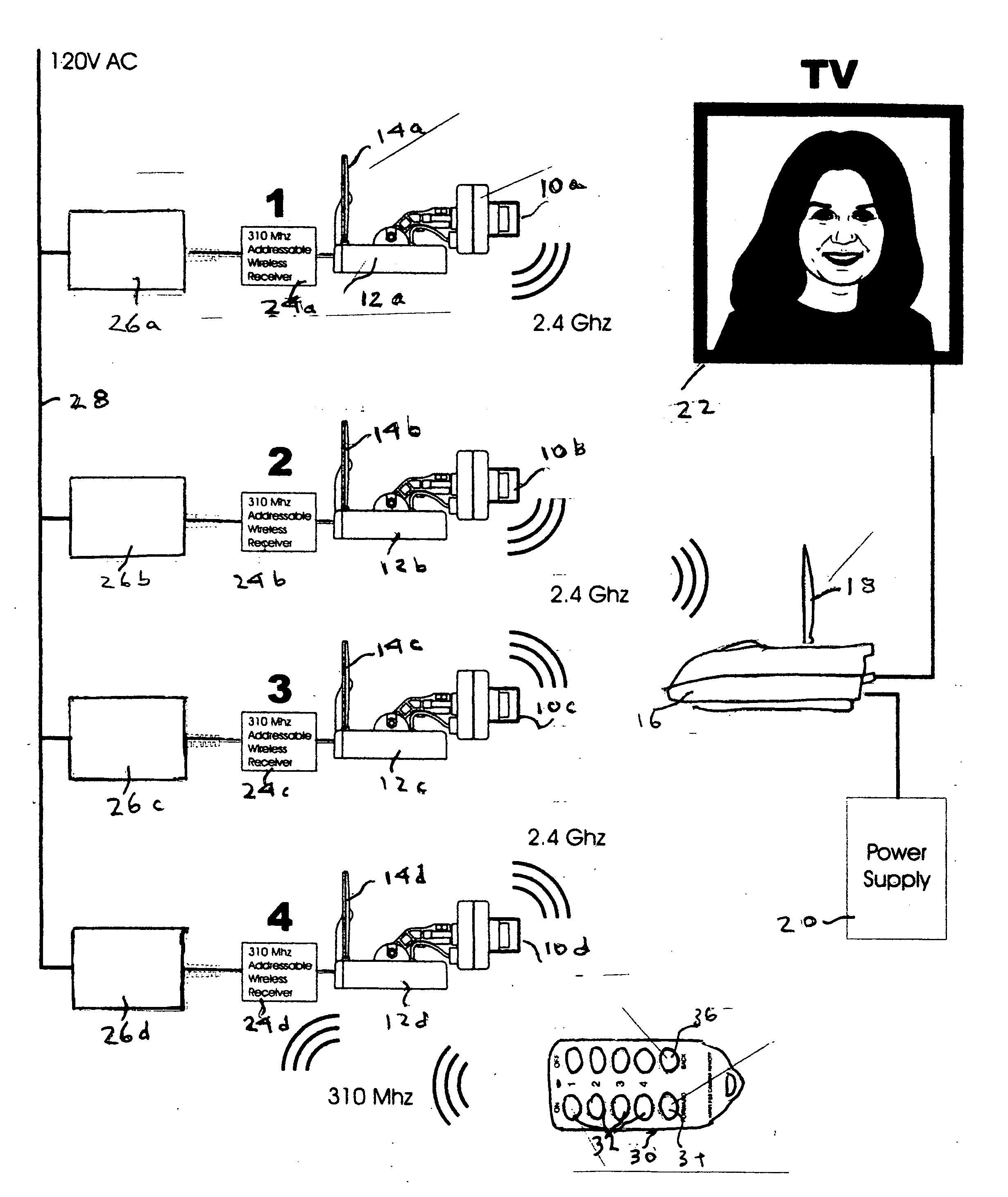
[0020] As illustrated in FIG. 1, a group of television or video cameras 10a-10d, here shown for purposes of example only as being four in number, are positioned at various selected, spaced locations in and around a home. One of the cameras 10 may be situated, for example, in a baby's room and another by a pool. Each camera 10 is preferably a miniaturized color video camera that preferably can be manually or mechanically moved through an arcuate path to enable it to scan over a relatively large area.

[0021] The video signal produced by each camera, when it is turned on in the manner described in greater detail in a later part of this specification, is applied to its associated 2.4 GHz wireless video sender 12a-12d to which is also respectively connected a 2.4 GHz patch antenna 14a-14d. The video sender 12 to which the then on video camera is connected transmits a video rf signal from its patch antenna at a typical frequency of 2.4 GHz to a 2.4 GHz video rf receiver 16, which receives...


PUM


Abstract

A wireless multi-camera home surveillance system includes a plurality of video cameras located at different locations in and around the home. The cameras are respectively connected to a plurality of wireless addressable rf receivers which receive over-the-air binary-coded rf address signals from a remote control unit. The addressed receiver applies an operating voltage to its associated camera to turn it on while all other cameras, including any previously on camera, are turned off.

Description

BACKGROUND OF THE INVENTION [0001] 1. Field of the Invention [0002] The present invention relates generally to surveillance systems, and more particularly to a wireless system for monitoring a plurality of different, spaced locations in a home, office or similar installation at a single viewing station. [0003] 2. Description of the Prior Art [0004] As described, for example, in U.S. Pat. No. 6,744,463 granted to the inventors herein and assigned to a common assignee herewith, the use of video cameras to monitor the comings and goings of individuals in a public building or multi-dwelling building has become widespread in recent years. In a security installation of this nature, video cameras are installed at various locations in the building. The video outputs of these cameras are coupled respectively to a corresponding plurality of television receivers at a single security station at which the images derived from these cameras can be viewed by a security officer who is thus able to v...

Claims


Application Information

Patent Timeline
Patent Type & Authority Applications(United States)
IPC IPC(8): H04N7/18H04N9/47
CPCG08B13/19645G08B13/1966G08B13/19695H04N7/181
Inventor RYE, DAVID JOHNLEECH, LESLEY ALAN
Owner X 10
Why Eureka
Try Eureka