
System and method for imaging enhancement via calculation of a customized optimal pupil field and illumination mode

a technology of optimal pupil field and illumination mode, applied in the direction of cathode-ray tube indicators, optics, photomechanical apparatus, etc., can solve the problems of reducing the effectiveness of the dynamic patterning device, imposed manufacturing constraints considered in the fabrication and use of the static patterning device,

Inactive Publication Date: 2006-08-03
ASML HLDG NV
View PDF22 Cites 16 Cited by
  • Summary
  • Abstract
  • Description
  • Claims
  • Application Information

AI Technical Summary

Benefits of technology

[0011] It is to be appreciated that the Summary represents one or more exemplary embodiments and / or examples, but not all embodiments and / or examples of the present invention, and thus should not be seen to be limiting the present invention, or the appended claims, in any way.

Problems solved by technology

For example, manufacturing constraints considered in the fabrication and use of the static patterning device are imposed on the dynamic patterning device.
Further, the various types of dynamic patterning devices have different operational characteristics, which are not taken into account when using the pattern data from the static patterning device to control the dynamic patterning device.
All this can lead to a reduction in the effectiveness of the dynamic patterning device to form desired patterns on the object.

Method used


Image

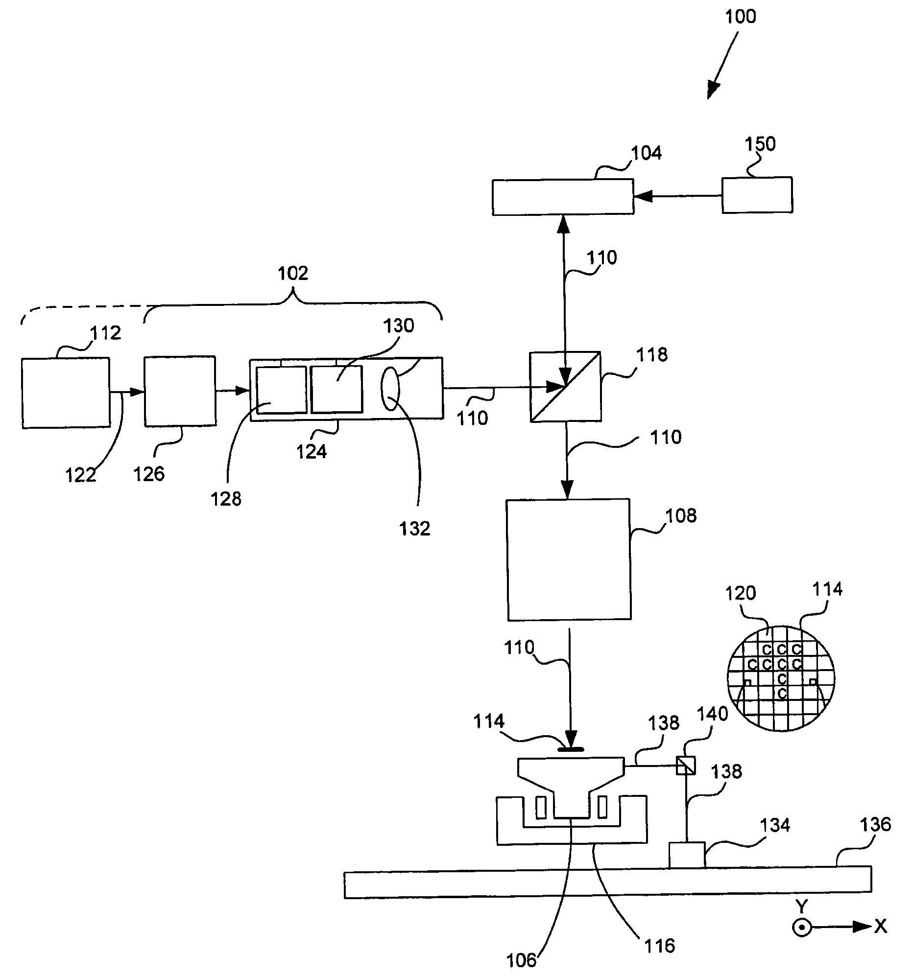
  • System and method for imaging enhancement via calculation of a customized optimal pupil field and illumination mode
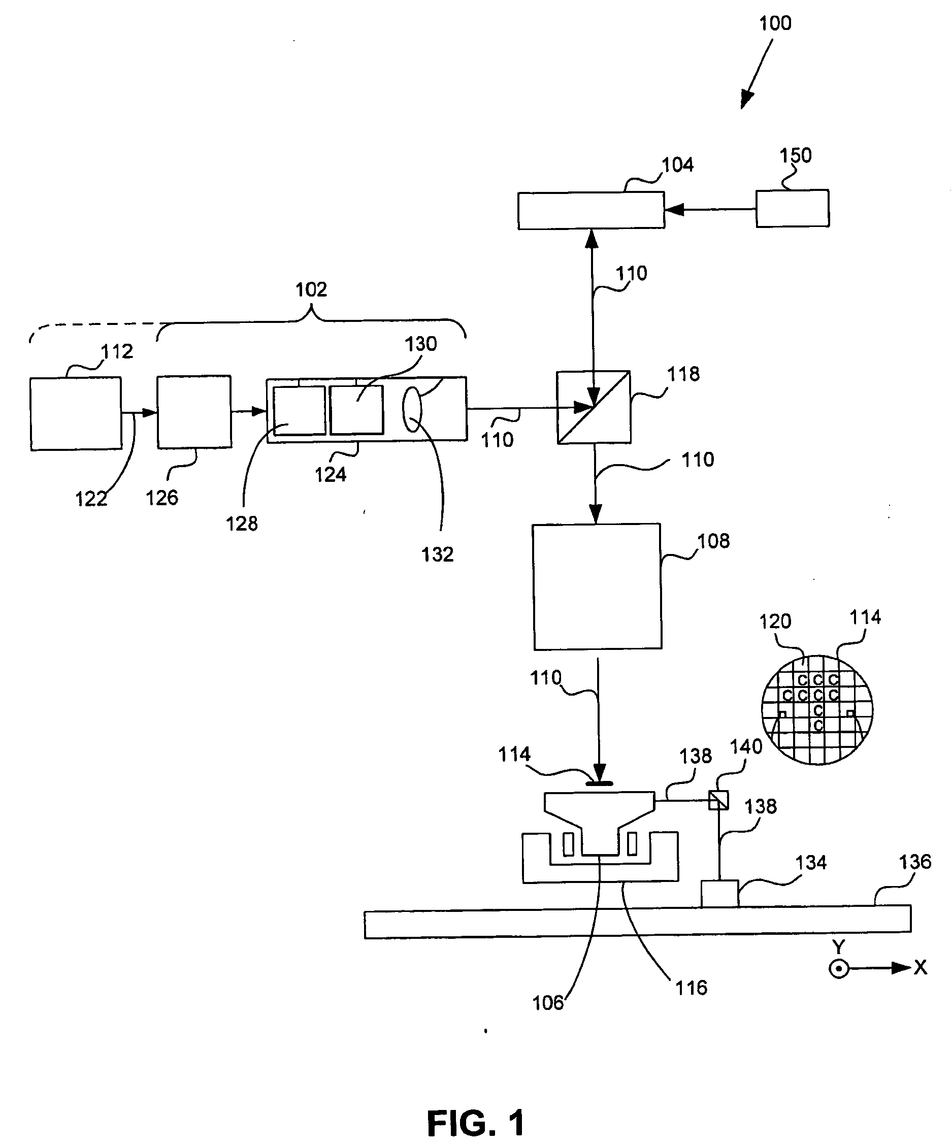
  • System and method for imaging enhancement via calculation of a customized optimal pupil field and illumination mode
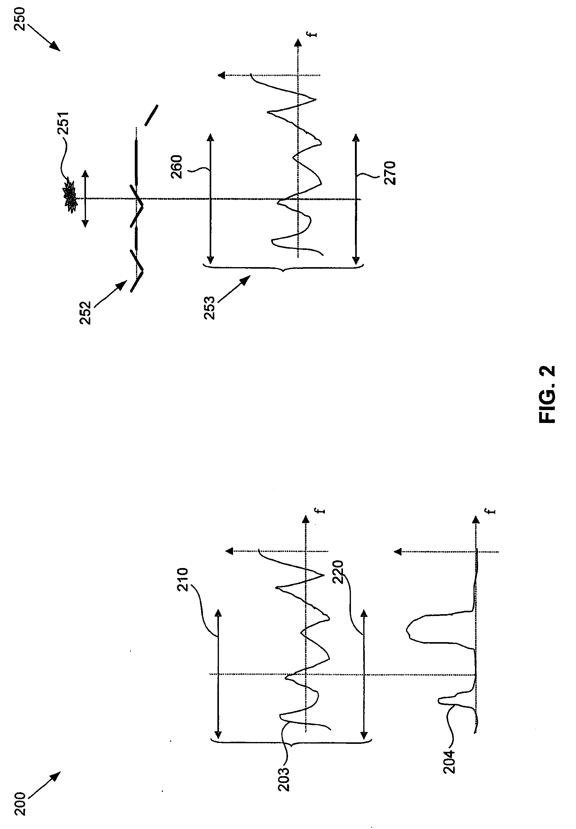
  • System and method for imaging enhancement via calculation of a customized optimal pupil field and illumination mode

Examples


example application

VI. Example Application

[0120] Optical Maskless Lithography (OML) can enable applications that are physically difficult if not impossible to realize with conventional mask-based lithography; aspects of the present invention allow the states of the SLM pixels to be calculated so that such applications can be realized. One of many examples of a physically difficult mask to manufacture is a vortex mask, which is a four-phase mask that has been proposed for contact hole applications. Simulations indicate that using additional phases, such as eight-phase or twelve-phase masks, which are impractical, if not impossible, to produce with current reticle technology, would have even higher performance than the four-phase mask. As will be apparent to persons having ordinary skill in the art, by using an aspect or aspects of the present invention, such a pattern, while nearly impossible to manufacture on a reticle, can be produced in an OML system with a contrast device capable of continuous phas...


PUM


Abstract

A system and method for patterning a beam of radiation based on a pupil field distribution. In an embodiment, the distribution of the field in an area of the pupil plane affecting an image and an illumination mode are selected so as to render an image with desired characteristics. Additionally and / or alternatively, an illumination mode is selected so as to render an image with desired characteristics. The distribution of the field in an area of the pupil plane affecting an image is then realized using the spatial light modulator The system and method include using an illumination system, a pattern generator, and a projector. The illumination system supplies a beam of radiation. The pattern generator patterns the beam of radiation based on a data set corresponding to a field distribution in a pupil plane. The projector projects the patterned beam onto a target portion of an object.

Description

BACKGROUND [0001] 1. Field of the Invention [0002] The present invention relates to a light patterning device and method of using the same. [0003] 2. Background Art [0004] A patterning device is used to pattern incoming light. A static patterning device can include reticles or masks. A dynamic patterning device can include an array of individually controllable elements that generate a pattern through receipt of analog or digital signals. The algorithm used to control the dynamic patterning device, so that its individually controllable elements are in a proper state to form a desired pattern, is called a rasterization algorithm or optical rasterization algorithm. Example environments for use of the patterning device can be, but are not limited to, a lithographic apparatus, a projector, a projection display apparatus, or the like. [0005] Pattern information for the dynamic patterning device is generated from the pattern data of a static patterning device. For instance, dynamic pattern...

Claims


Application Information

Patent Timeline
Patent Type & Authority Applications(United States)
IPC IPC(8): G09G3/00
CPCG03F7/70116
Inventor LATYPOV, AZAT M.CEBUHAR, WENCESLAO A.HINTERSTEINER, JASON D.
Owner ASML HLDG NV
Learn More