
Medical device

a technology of medical devices and devices, applied in the field of medical devices, can solve the problems of loss of motion, complicated structure of moving means arranged outside the body, and control operation,

Active Publication Date: 2006-08-03
OLYMPUS CORP
View PDF20 Cites 69 Cited by
  • Summary
  • Abstract
  • Description
  • Claims
  • Application Information

AI Technical Summary

Benefits of technology

The present invention is a medical device that is inserted into a body cavity. It has a part that is shaped like a spiral and that helps to generate thrust in contact with the cavity. The spiral has certain characteristics, such as a pitch of 10 mm or more, a height of 0.3 mm or more and 3 mm or less, a cross-sectional shape that is almost half-circular or almost trapezoidal, an inclining angle of an end portion of 45° or less, and a number of spirals that is 2 or more and 10 or less. These characteristics are important for the device to function properly and safely in the body.

Problems solved by technology

However, the first conventional art has the following problems.
Therefore, the moving means arranged outside the body has the complicated structure and the control operation.
Further, the capsule endoscope does not have the thrust generating unit for converting rotating force into the thrust on the outer surface.
Therefore, the lost motion is caused in the body cavity in many cases and the stable thrust is not obtained.
Therefore, if the disclosed contents are directly applied, the following problems are caused.
(a) The shape of the thrust generating unit (spiral, screw, or drill) is not optimal and therefore the lost motion is caused in a non-contact state with the inner wall in the body cavity.
(b) The optimal magnetic torque is not considered and therefore the torque is not sufficiently obtained, or the magnetic torque more than necessary is obtained but an extra-body device is increased in size.

Method used


Image

  • Medical device
  • Medical device
  • Medical device

Examples


first embodiment

[0047] The first embodiment of the present invention will be described with reference to FIGS. 1 to 23B.

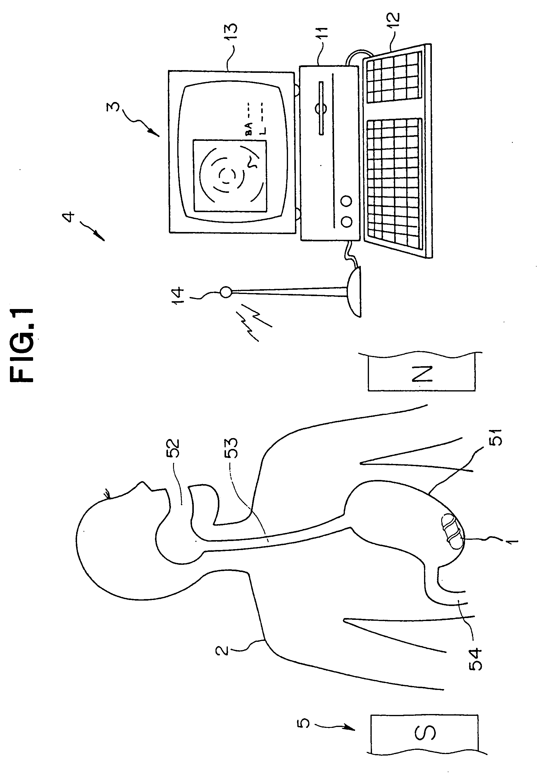
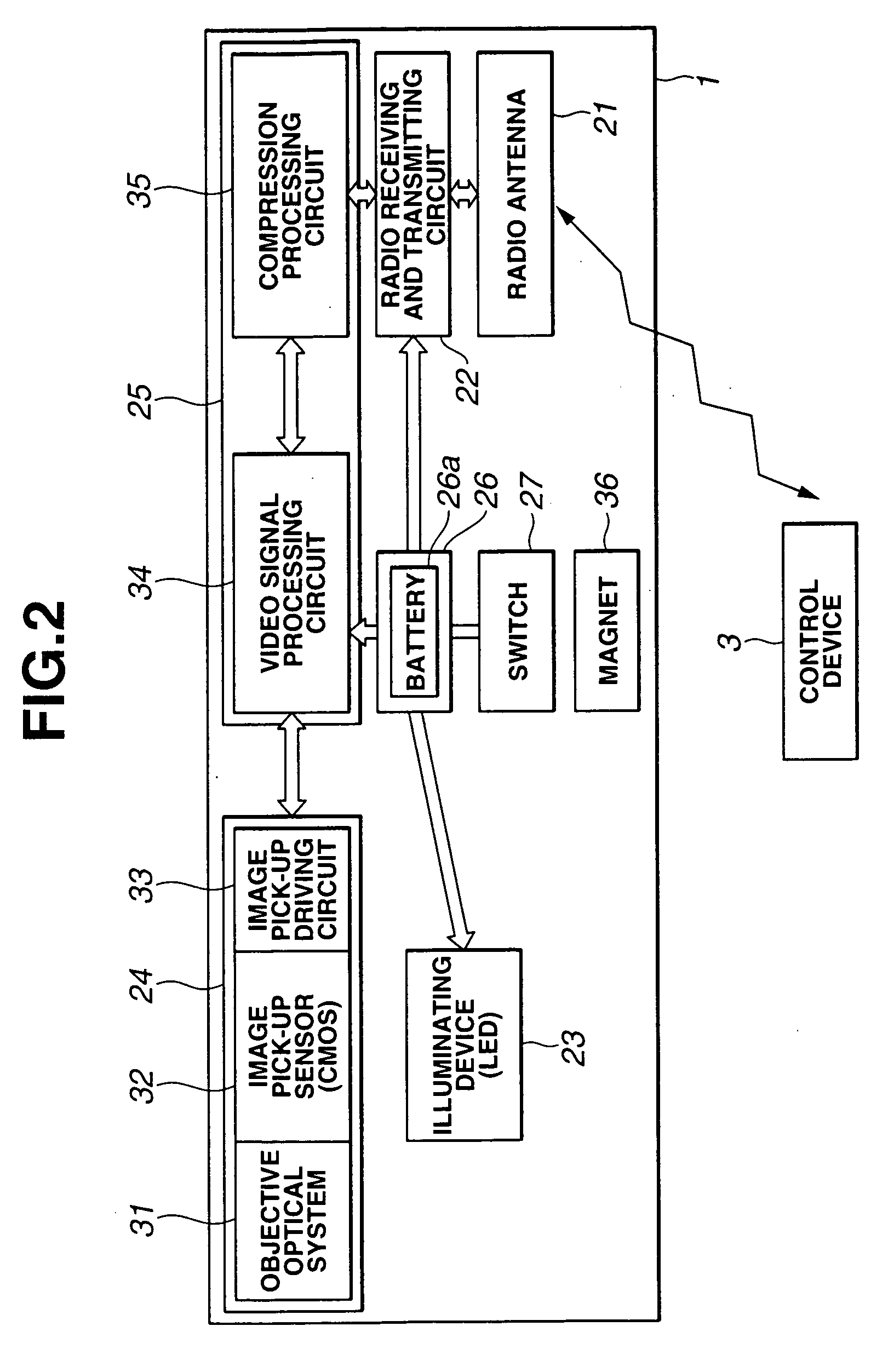
[0048] Referring to FIG. 1, a capsule medical apparatus 1 having a body cavity inserting portion which is inserted in the body cavity forms a medical system 4 which receives electric waves from / to a capsule control device (hereinafter, referred to as a control device) 3 arranged outside the body during the passage of the luminal portion in the body cavity of a patient 2 and thus can perform medical actions such as examination, curing, and treatment under the control of the control device 3.

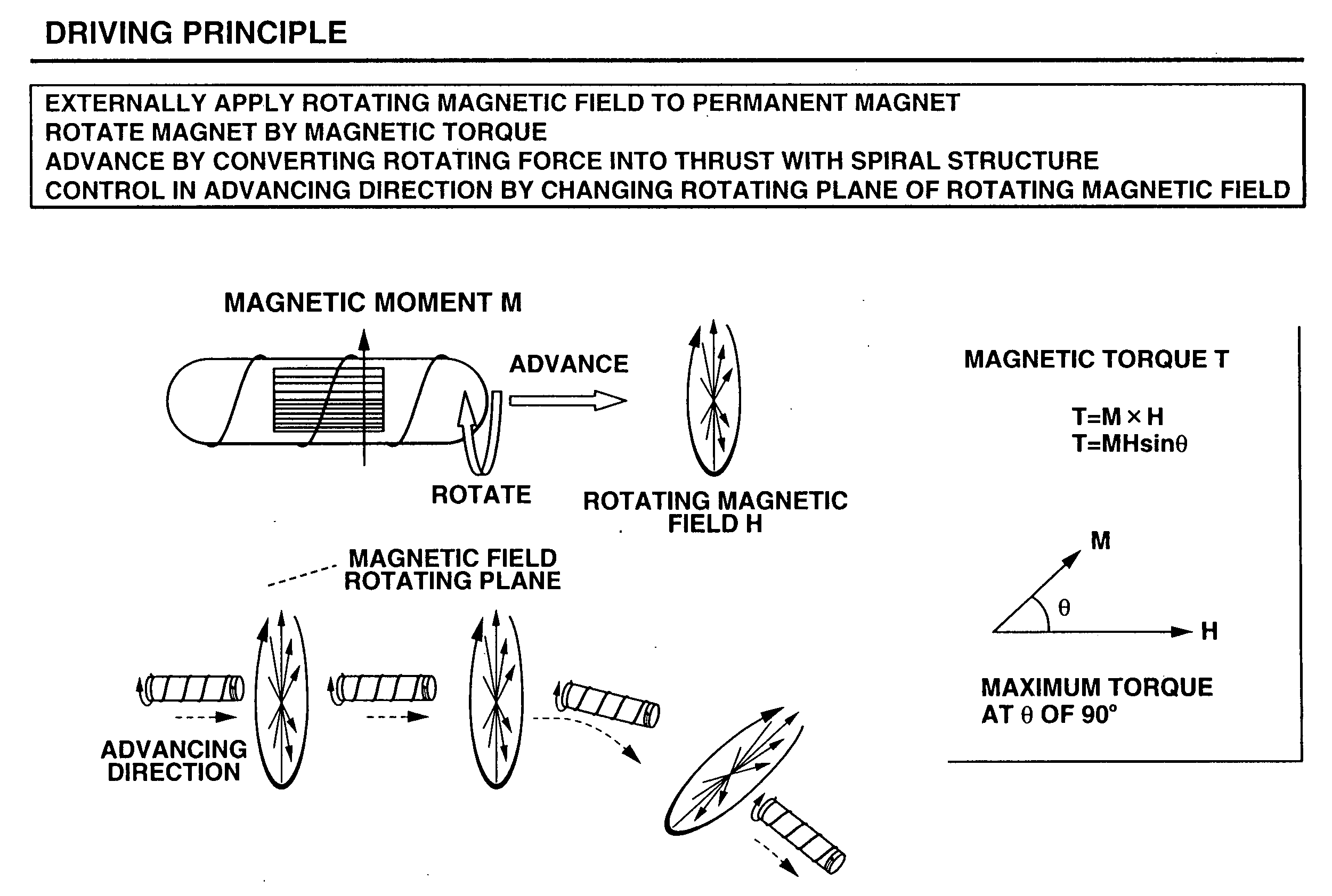
[0049] The medical system 4 has a magnetic guiding device 5, as magnetic field generating means, which generates a rotating magnetic field around the patient 2. The magnetic guiding device 5 smoothly advances the capsule medical apparatus 1 having the body cavity inserting portion in the body cavity of the patient 2. In FIG. 1, the magnetic guiding device 5 is schematically shown.

[0050] The m...

second embodiment

[0189] Next, the second embodiment of the present invention will be described with reference to FIGS. 24 and 25.

[0190] Referring to FIGS. 24 and 25, a capsule medical apparatus 80 according to the second embodiment comprises: a capsule main body 81; and a flexible string portion 82 which is inserted along the central axis of the capsule main body 81. The outer peripheral surface of the capsule main body 81 has a spiral projected portion 83b.

[0191] Referring to FIG. 25, the capsule main body 81 has a hollow hole along the central axis. Both ends of a hard rod 85 are rotatably supported to the capsule main body 81 by a bearing 84 such as a ball bearing. The hard rod 85 is inserted into the hollow hole and both ends of the hard rod 85 are connected to the flexible string portion 82.

[0192] In this case, one flexible string portion 82 is shortly extended from the capsule main body 81. The other flexible string portion 82 is extended long and the end portion thereof has taper-shaped th...


PUM


Abstract

A capsule medical apparatus inserted in the body cavity includes a spiral projected portion on the outer peripheral surface of a body cavity inserting portion. The pitch, height, and cross section of the projected portion and the like are set to have proper values and shapes suitable to the advance thereof. The body cavity inserting portion has a magnet. An external magnetic guiding device applies a rotating magnetic field to the magnet and the magnetic torque acts on a magnet 36 for rotation. Thus, the medical apparatus stably advances.

Description

TECHNICAL FIELD [0001] The present invention relates to a medical apparatus which rotates and advances in the body cavity by a rotating magnetic field or the like. BACKGROUND ART [0002] Japanese Patent No. 3017770 discloses a medical apparatus as a first conventional art for magnetically guiding in a sample. [0003] According to the first conventional art, the medical apparatus comprises a guided portion which is magnetically guided at least to a part of an inserting portion inserted in the sample, and moving means which moves magnetic force generating means arranged out of the sample in the direction that balances in the one guided direction and in the direction that cannot control the balance. [0004] Further, Japanese Patent No. 3017770 discloses a method for magnetically guiding a general endoscope inserting portion or a capsule endoscope. Furthermore, Japanese Patent No. 3017770 discloses a method for vibrating the endoscope inserting portion by an AC magnetic field and rotating ...

Claims


Application Information

Patent Timeline
Patent Type & Authority Applications(United States)
IPC IPC(8): A61B19/00A61B1/06A61B1/00A61B1/05A61B1/273A61B5/06A61B5/07
CPCA61B1/00016A61B1/00032A61B1/00156A61B1/00158A61B1/041A61B1/2736A61B5/06A61B5/073A61B2019/2253A61B5/7232A61B34/73A61B1/00
Inventor YOKOI, TAKESHITAKIZAWA, HIRONOBUUCHIYAMA, AKIOARAI, KENICHIISHIYAMA, KAZUSHISENDOU, MASAHIKO
Owner OLYMPUS CORP
Learn More