
Liquid crystal display device

a liquid crystal display and display device technology, applied in the field of liquid crystal display devices, can solve the problems of reducing display quality, burning images, and not being able to reduce the dc component to zero, and achieve the effect of accurate adjustment and stable image quality

Active Publication Date: 2006-07-27
FUNAI ELECTRIC CO LTD
View PDF8 Cites 9 Cited by
  • Summary
  • Abstract
  • Description
  • Claims
  • Application Information

AI Technical Summary

Benefits of technology

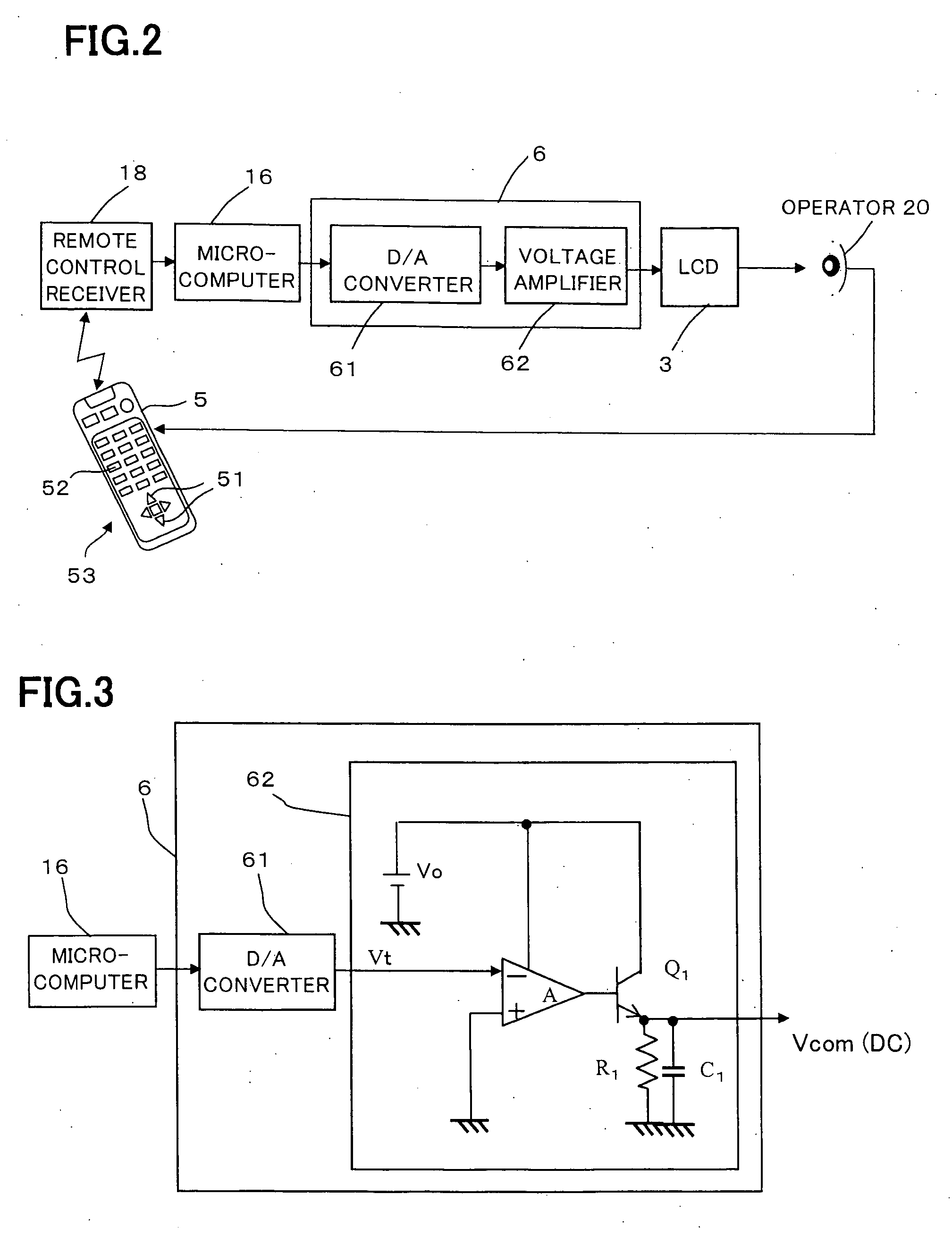
[0018] An object of the present invention is to provide a liquid crystal display device that allows an operator (human) to adjust flicker using a remote controller in actual adjustment work at a position where the operator can easily view a display screen of the liquid crystal display device, and to make the adjustment accurately by remote control, thereby achieving an inexpensive liquid crystal display device with stable image quality.
[0020] The liquid crystal display device according to the present invention makes it possible for an operator (human) to make flicker adjustment using the remote controller, at a position on the front side of, and if necessary distanced from, the liquid crystal display unit where the operator can directly and easily view an image on the liquid crystal display unit. As compared with the conventional adjustment work using a variable resistor, the operator can make the flicker adjustment much more easily and accurately. Since this makes it unnecessary to use a mirror to adjust a variable resistor in contrast to the conventional adjustment work, it is particularly effective in the case of a liquid crystal display device with a large-sized display screen. In addition, the liquid crystal display device of the present invention enables the operator to make the flicker adjustment from outside, so that it is not necessary to open the case of the liquid crystal display device for the flicker adjustment. Thus, even if the liquid crystal display device is already in the form of a finished product, it is possible to easily make the flicker adjustment at any time if necessary.

Problems solved by technology

This reduces the display quality, and significantly degrades the property of the liquid crystal, which sometimes causes a burned-in image.
Accordingly, it is not possible to reduce the DC component to zero for the full range of gradation.
In addition, when a drive signal for the AC drive becomes asymmetric due to the superimposition of the DC component, flicker occurs at the same period as that of the frequency of the driving signal.
However, it is difficult for any of such available drive modes to completely reduce the flicker, so that some additional adjustment for reducing the flicker is needed.
Accordingly, it is difficult for the operator to turn the knob of the variable resistor Rx for the adjustment with its hand stretched out while viewing the display screen.
This is particularly so when the display screen is large-sized, so that the adjustment is difficult.
However, an adjustment work using a mirror is not easy, particularly when the display screen is large-sized.
With a large-sized display screen and a mirror, it is significantly difficult to view and inspect the flicker on the display screen, resulting in a long time for the adjustment and reduction of adjustment accuracy.
In addition, the variable resistor Rx reduces its reliability if turned many times for the adjustment.
However, this LCD device requires a wired remote controller to be exclusively used for the counter-electrode voltage adjustment, and also requires many circuit elements for the flicker detection, data storage, data processing and so on for the purpose of the automatic adjustment.
This results in increased circuit complexity and increased cost, and causes power consumption to increase due to the increased circuit size.
In addition to this problem, the LCD device has a further problem that the wired remote controller can move only in a limited range because of the wiring, and is harder to use than an ordinary remote controller by wireless or light transmission.
This causes a problem that it is difficult to make the counter-electrode voltage adjustment, particularly for a large-sized display, just as the above-described conventional LCD television receiver.
This causes a problem that it requires use of multiple photosensors to achieve high detection accuracy, and also requires alignment accuracy of the photosensors, resulting in increased circuit complexity and increased cost.

Method used


Image

  • Liquid crystal display device
  • Liquid crystal display device
  • Liquid crystal display device

Examples


first embodiment

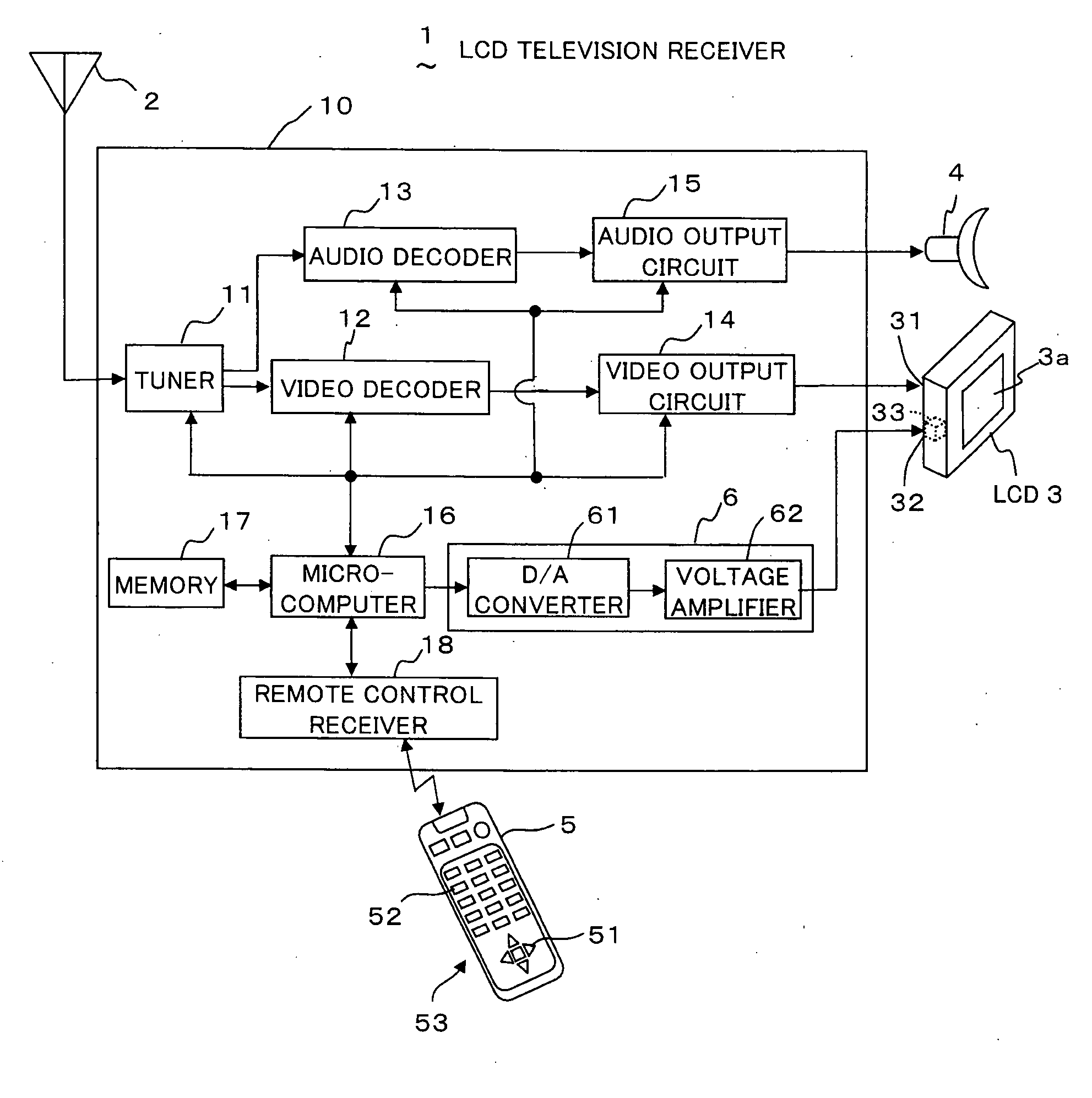
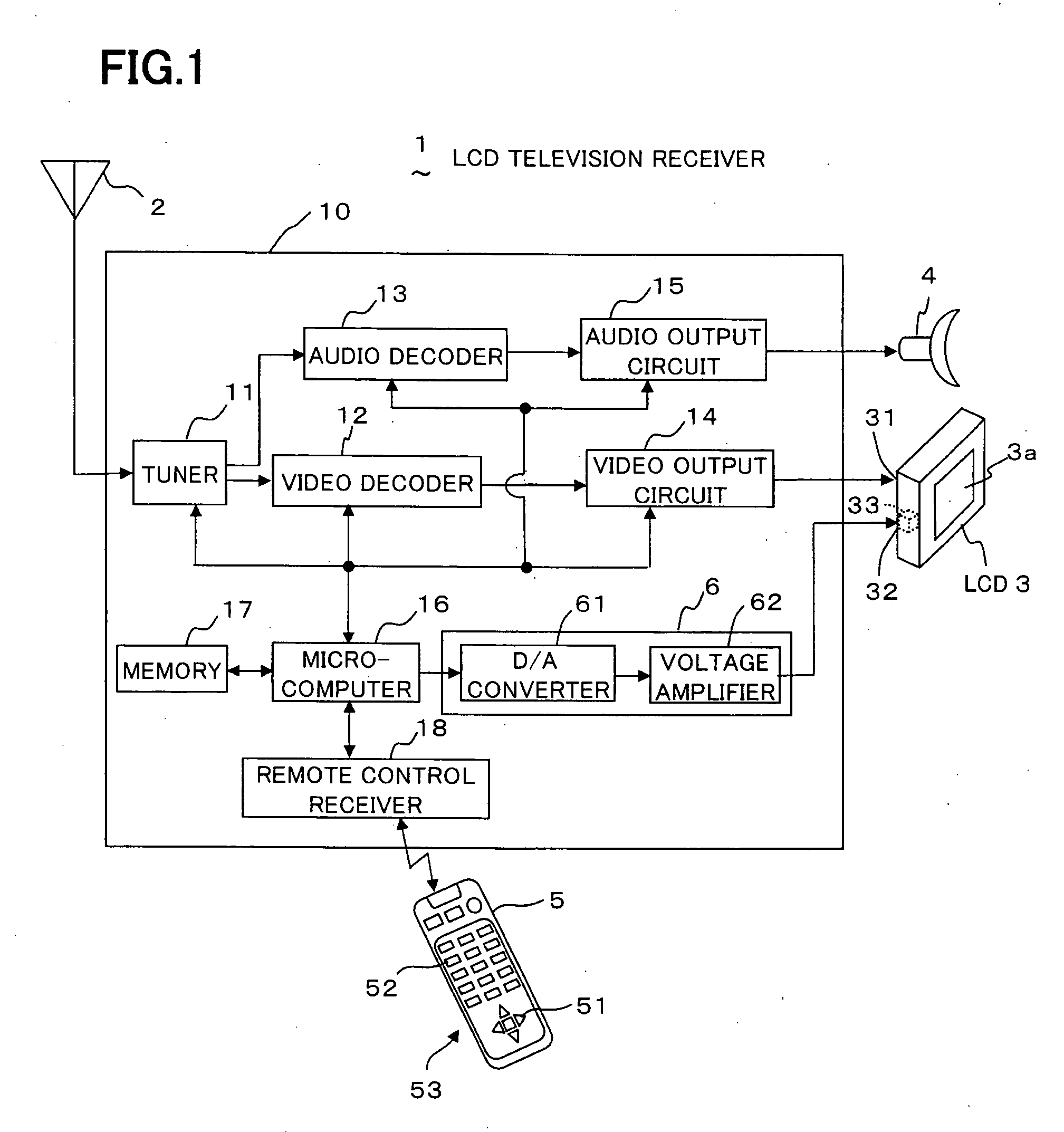
[0035]FIG. 1 is a schematic block diagram of a liquid crystal display (hereafter referred to as “LCD”) television receiver 1 as an LCD device according to the present invention. Referring to FIG. 1, the LCD television receiver 1 comprises a television receiver body 10, an antenna 2, an active matrix type liquid crystal display (“AM-LCD”) 3 (claimed liquid crystal display unit) with a liquid crystal panel 3a of active matrix type for displaying images, a speaker 4 for outputting sounds, and a remote control unit 5 (claimed remote controller).

[0036] The television receiver body 10 comprises: a tuner 11 for selecting a channel in television signals from the antenna 2 by operating an up / down key 51 and / or a ten key 52 (e.g. numeric keys of 1 to 16) in a key unit 53 of the remote control unit 5; a remote control receiver 18 for receiving controls signals from the remote control unit 5 to e.g. the tuner 11; a video decoder 12 for decoding a video signal; an audio decoder 13 for decoding a...

second embodiment

[0048] Since the LCD television receiver 70 of the present invention has such function as described above, an operator (human) can make flicker adjustment while viewing not only amount of flickering of the checkered pattern displayed in the test pattern display area 83, but also color displayed in the color bar display area 82. Thus, the LCD television receiver 70 facilitates easy flicker adjustment by the operator, and in addition, reduction of adjustment variation due to different operators.

[0049] It is to be noted that the present invention is not limited to the above embodiments, and various modifications are possible. For example, in the embodiments described above, a power supply of 3.3 V is used to operate the microcomputer 16. However, a power supply e.g. of 5.0 V can be used instead. Since the power supply of 5.0 V enables use of a higher driving voltage, the use of the power supply of 5.0 V makes it possible to apply the output voltage from the D / A converter 61 directly to...


PUM


Abstract

An LCD device operated by a remote controller comprises: an LCD unit having a display electrode supplied with voltage based on a video signal and a counter-electrode supplied with counter-electrode voltage; a remote control receiver for receiving a flicker adjustment control signal from the remote controller; a microcomputer for outputting a flicker voltage control signal based on the flicker adjustment control signal; a counter-electrode voltage control unit for generating a flicker adjustment voltage whose value varies according to the flicker voltage control signal, and outputting a DC counter-electrode voltage based on the flicker adjustment voltage; and a DC-AC converter for converting the DC counter-electrode voltage to AC voltage to be applied to the counter-electrode. An operator (human) can make flicker adjustment at a position on the front side of, and if necessary distanced from, the LCD device where the operator can directly and easily view an image on the LCD.

Description

BACKGROUND OF THE INVENTION [0001] 1. Field of the Invention [0002] The present invention relates to a liquid crystal display device to be subjected to counter-electrode voltage adjustment work, and more particularly to a technology of flicker adjustment for an active matrix type liquid crystal display device using a remote controller. [0003] 2. Description of the Related Art [0004] Generally, an active matrix type liquid crystal display (hereafter referred to simply as “AM-LCD”) is often used for a liquid crystal display device such as an LCD television receiver or an LCD projection television receiver. The AM-LCD device is typically formed such that a liquid crystal layer is sandwiched between a pair of substrates to be a liquid crystal panel, that a plurality of gate lines and a plurality of source lines are formed on one of the substrates, and that a TFT (Thin Film Transistor) is provided as a switching element at each intersection between each gate line and each source line for...

Claims


Application Information

Patent Timeline
IPC IPC(8): G09G3/36
CPCG09G3/3655H04N21/4221H04N2005/4428G09G2320/0247H04N21/42222
Inventor NAKAMURA, YUSUKE
Owner FUNAI ELECTRIC CO LTD
Learn More