Steering apparatus
a technology of steering apparatus and pinion shaft, which is applied in the direction of mechanical equipment, couplings, transportation and packaging, etc., can solve the problems of reducing the steering stability of the steering wheel, affecting the stability so as to achieve the effect of improving the steering stability and reducing the vibration and bending moments of the pinion shaft and the pinion sha
- Summary
- Abstract
- Description
- Claims
- Application Information
AI Technical Summary
Benefits of technology
Problems solved by technology
Method used
Image

Examples
first embodiment
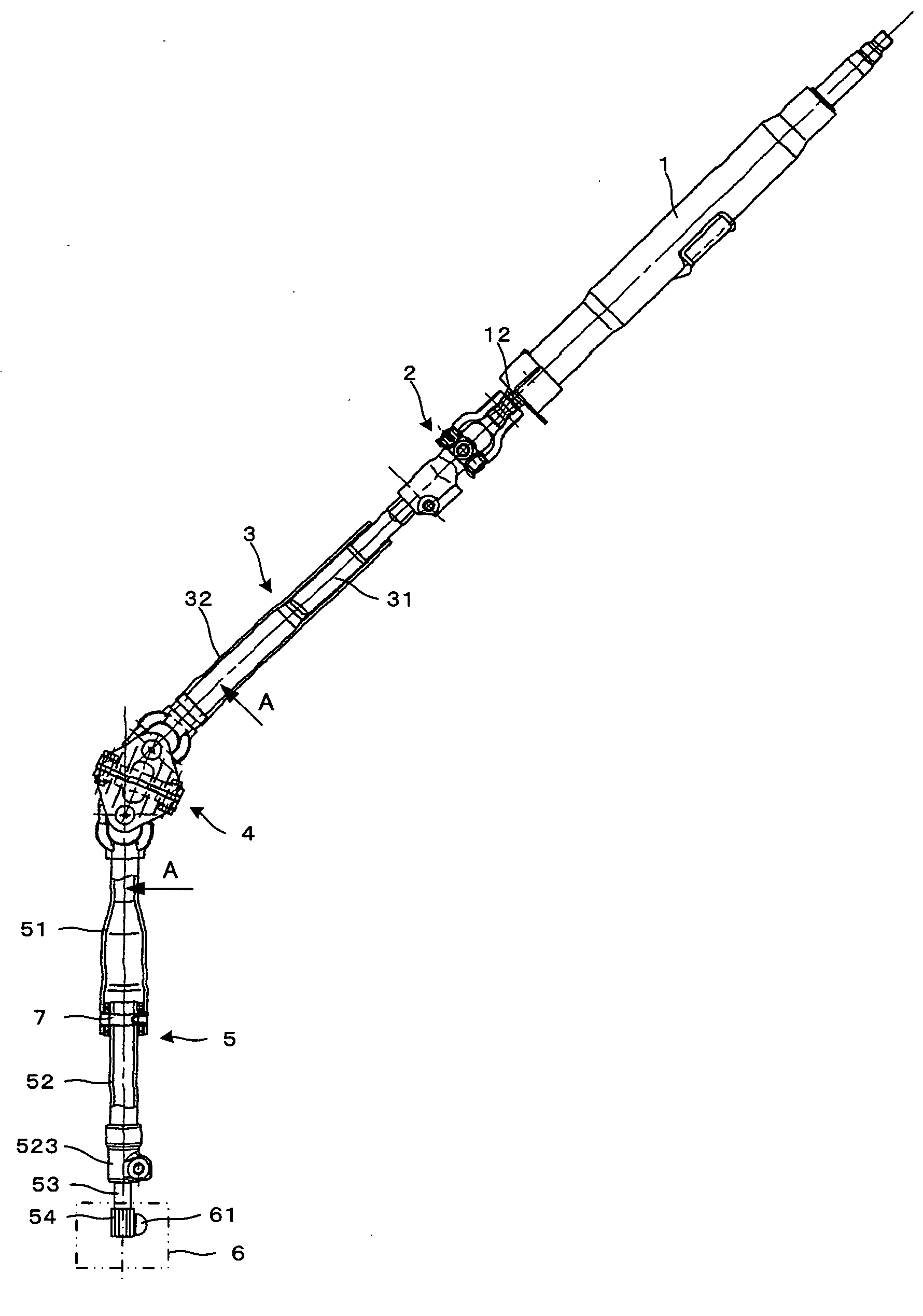
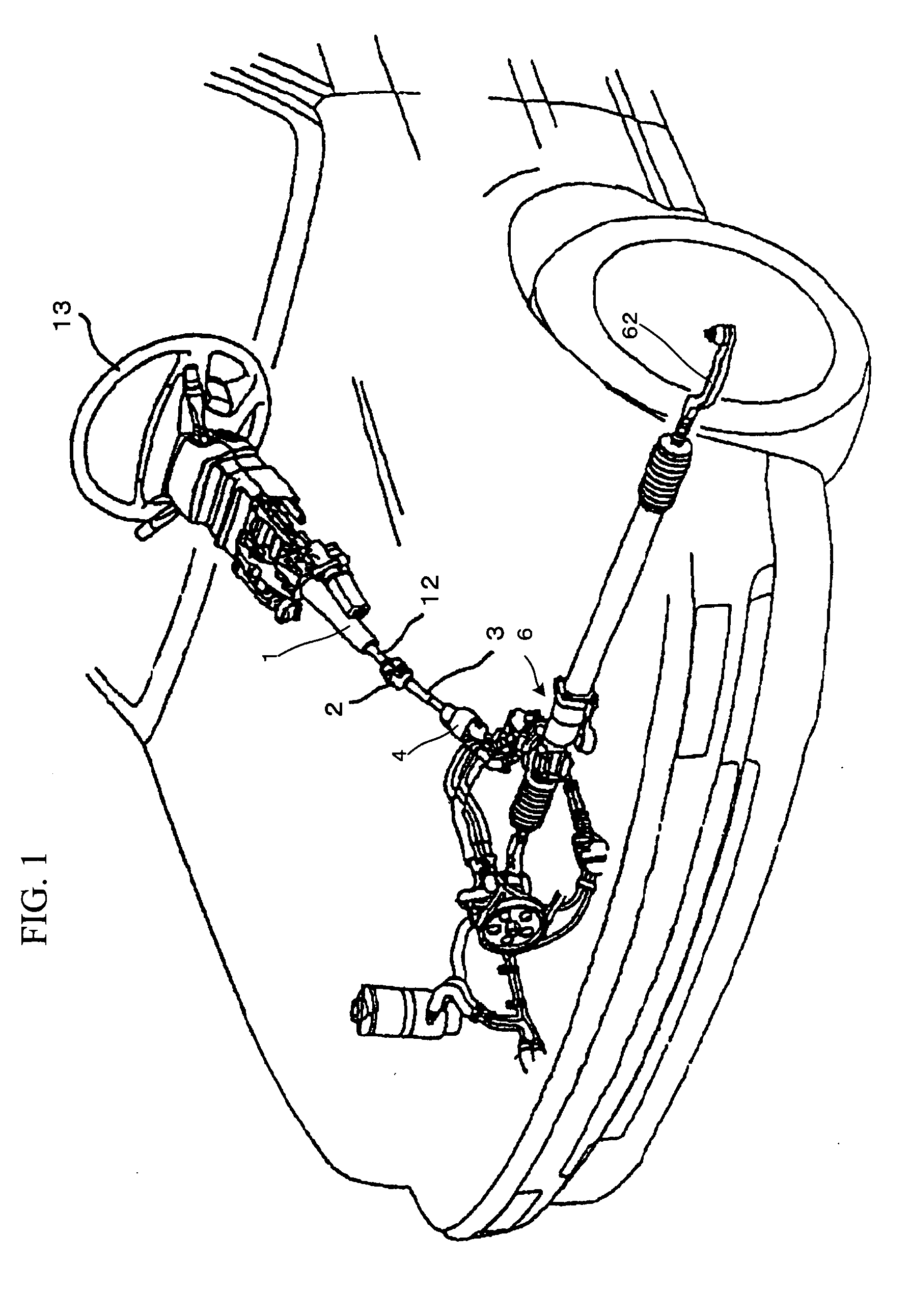
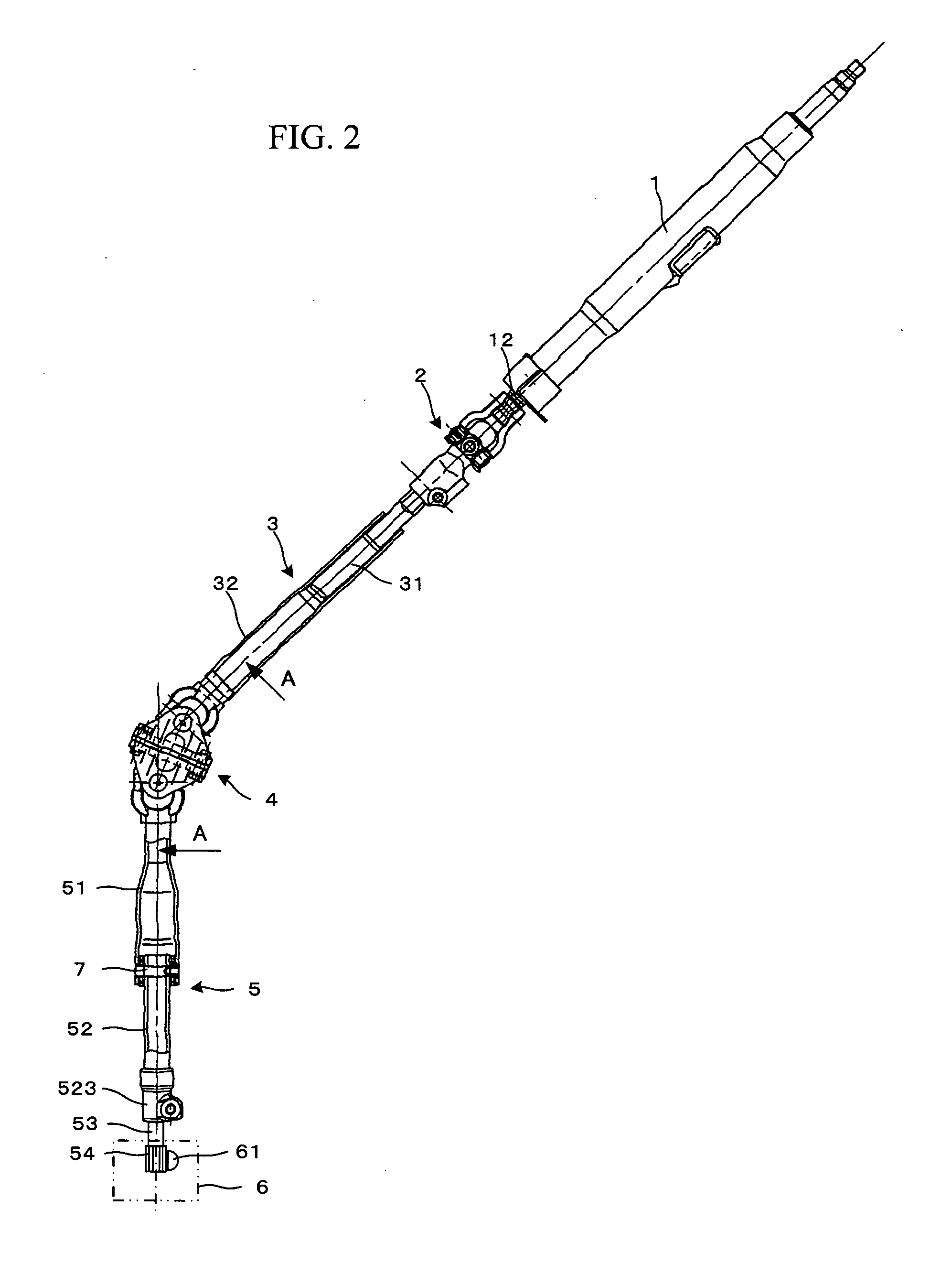
[0022] A first embodiment of the present invention will be described in the following with reference to the accompanying drawings. FIG. 1 is an overall perspective view showing a steering apparatus according to the present invention in a state of being mounted on a vehicle. FIG. 2 is a partly sectional side elevation view showing principal parts of a steering apparatus according to the first embodiment of the present invention. FIG. 3 is an enlarged sectional view of a double Cardan constant velocity universal joint shown in FIG. 2, taken along line A—A thereof. FIG. 4 is a sectional view of the double Cardan constant velocity universal joint in a state reached when a steering shaft in the state shown in FIG. 3 is rotated by 90 degrees. FIG. 5 is an enlarged sectional view of an elastic coupling shown in FIG. 2.
[0023] As shown in FIGS. 1 and 2, a cylindrical column 1 is fixed to a vehicle body and a steering shaft 12 is rotatably and axially supported by the column 1. A steering wh...
second embodiment
[0050] Next, a second embodiment of the present invention will be described. FIG. 6, which is equivalent to FIG. 2 for the first embodiment, is a partly sectional side elevation view showing principal parts of a steering apparatus according to the second embodiment of the present invention. FIG. 7 is an exploded perspective view of an elastic coupling shown in FIG. 6. In the following, only parts of the steering apparatus of the present embodiment configured differently from those used in the first embodiment will be described. Description which duplicates the foregoing description will be omitted. Parts identical with those used in the first embodiment will be denoted by the same reference numerals as used in describing the first embodiment. The elastic coupling used in the first embodiment is of a stopper pin type. The elastic coupling used in the second embodiment is of a coupling type.
[0051] As shown in FIGS. 6 and 7, in the steering apparatus according to the second embodiment...
third embodiment
[0065] Next, a third embodiment of the present invention will be described. FIG. 8, which is equivalent to FIG. 2 for the first embodiment, is a partly sectional side elevation view of a steering apparatus according to the third embodiment of the present invention. In the following, only parts of the steering apparatus of the present embodiment configured differently from those used in the foregoing embodiments will be described. Description which duplicates the foregoing description will be omitted. Parts identical with those used in the foregoing embodiments will be denoted by the same reference numerals as used in describing the foregoing embodiments.
[0066] The third embodiment represents a case in which a variable gear ratio steering (VGRS) device is provided between a double Cardan constant velocity universal joint 4 and an extension shaft 5, the variable gear ratio steering (VGRS) device being for changing a ratio between a steering angle of a steering wheel and a turning ang...
PUM
 Abstract
Description
Claims
Application Information
 - R&D
- Intellectual Property
- Life Sciences
- Materials
- Tech Scout
- Unparalleled Data Quality
- Higher Quality Content
- 60% Fewer Hallucinations
Browse by: Latest US Patents, China's latest patents, Technical Efficacy Thesaurus, Application Domain, Technology Topic, Popular Technical Reports.
© 2025 PatSnap. All rights reserved.Legal|Privacy policy|Modern Slavery Act Transparency Statement|Sitemap|About US| Contact US: help@patsnap.com