
Humidifier

a technology of humidifiers and humidifiers, which is applied in the field of humidifiers, can solve the problems of long-term cough, dry skin, scratchy throats, and inability to clean the air in the home,

Inactive Publication Date: 2006-07-27
HUNTER FAN
View PDF99 Cites 47 Cited by
  • Summary
  • Abstract
  • Description
  • Claims
  • Application Information

AI Technical Summary

Benefits of technology

[0006] In a preferred form of the invention, a humidifier comprises a housing defining a water reservoir configured to provide a select maximum water level, an air intake, an air outlet, and an air channel extending between the air intake and the air outlet. The air channel has a downward channel portion, an upward channel portion, and a junction portion extending between the downward channel portion and the upward channel portion. The junction channel portion is positioned above the reservoir select maximum water level. The humidifier also has a motorized fan positioned to create an airflow through the air channel from ...

Problems solved by technology

This often results in the inhabitants of the home developing one or more problems including dry skin, scratchy throats and long term coughs.
In addition, the contents of the home may lose moisture which may cause furniture to creak, floors to squeak and a build-up of static electricity.
A common problem associated with these cool mist type humidifiers is that the droplets are carried by the airstream where they are then deposited upon furniture or other objects within the room.
The eventual evaporation of these droplets upon the furniture leaves a white mineral deposit which is unsightly and therefore must be removed periodically.

Method used


Image

  • Humidifier
  • Humidifier
  • Humidifier

Examples


Embodiment Construction

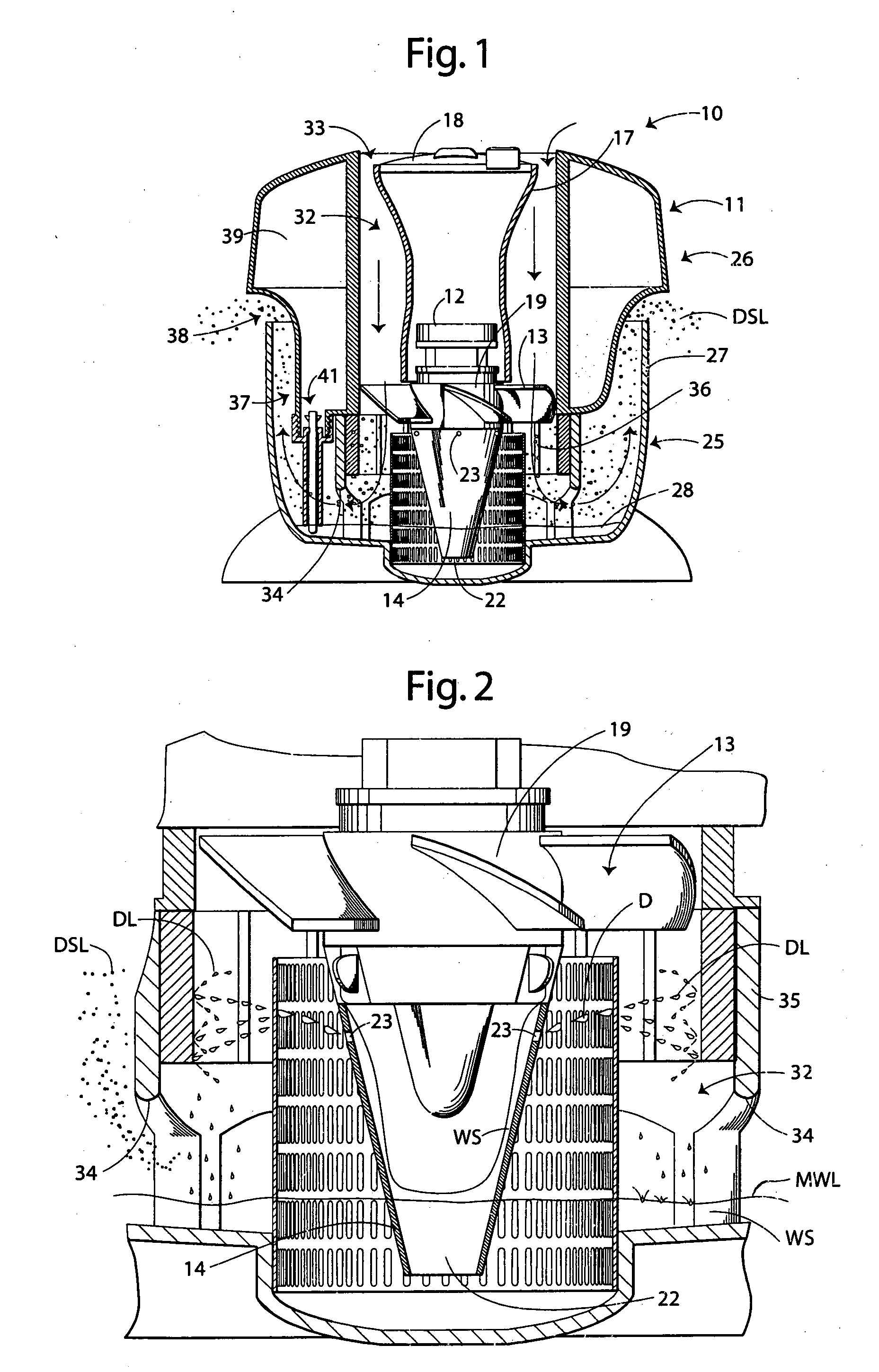
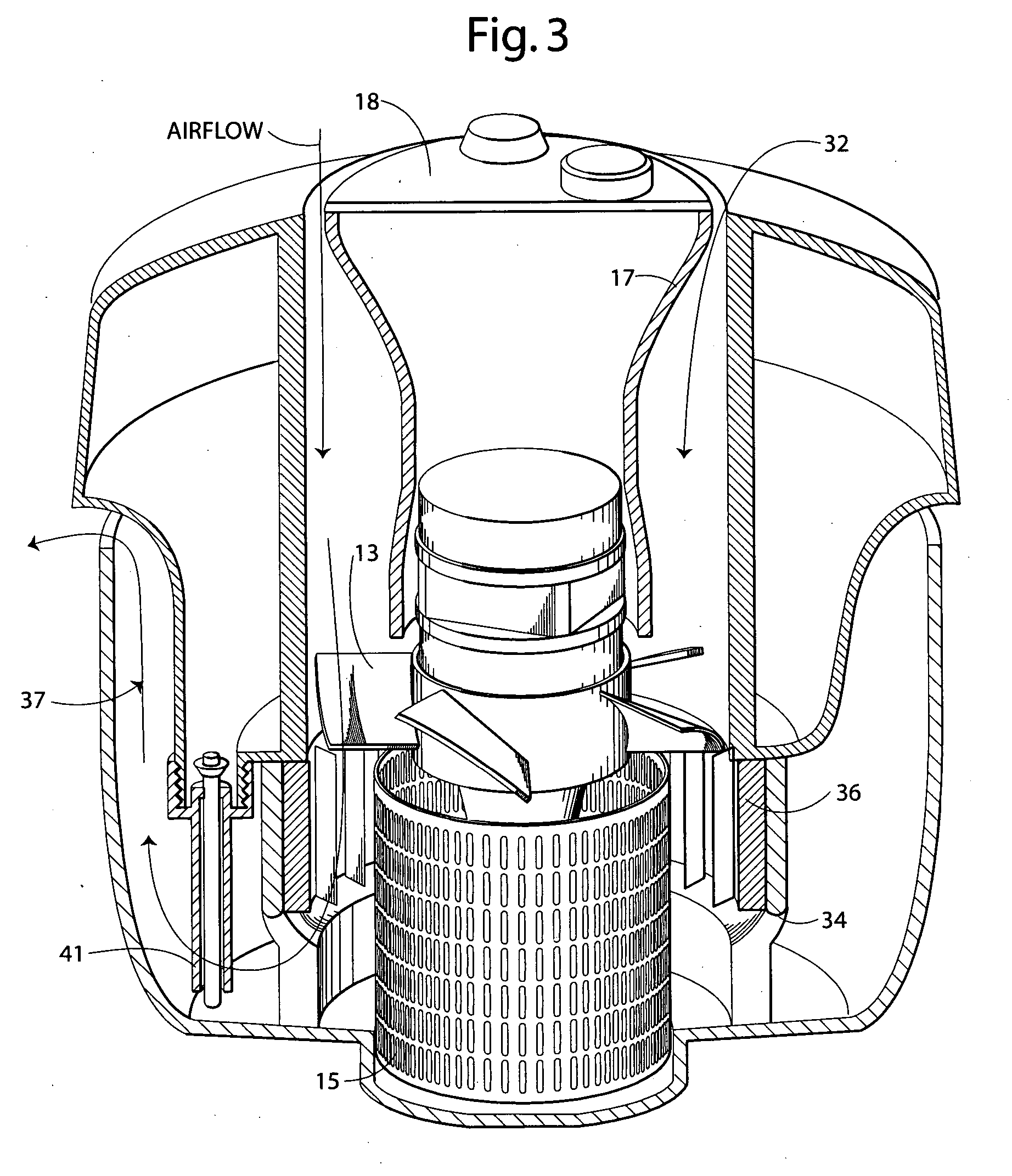
[0010] With reference next to the drawings, there is shown a humidifier 10 embodying principles of the invention in a preferred form. The humidifier 10 has a housing 11, a conventional electric motor 12 coupled to a conventional electric power source, a fan blade assembly 13 coupled to the electric motor 12, a conical suction tube 14 coupled to the electric motor 12 through the fan blade assembly 13, and a cylindrical water droplet diffusing screen 15 mounted concentrically about the suction tube 14.

[0011] The motor 12 is encased within a motor housing 17 having a top surface 18 to which conventional humidifier electronics may be coupled, such as the motor speed switch, desired humidification level, on / off switch and other similar electronics. The motor housing 17 is configured to extend flush with a central hub 19 of the fan blade assembly 13.

[0012] The suction tube 14 is coupled to the bottom of the fan blade assembly central hub 19. The suction tube 14 has a bottom opening 22 t...


PUM


Abstract

A humidifier (10) is provided having a housing (11), a conventional electric motor (12), a fan blade assembly (13), a conical suction tube (14), and a cylindrical water droplet diffusing screen (15) mounted concentrically about the suction tube. The housing defines a downward air channel (32) commencing at an air inlet (33) and which extends about the bottom edge (34) of a barrier to an upward air channel (37) terminating at an air outlet (38). The suction tube has a bottom opening (22) through which water may enter the interior space of the suction tube and a series of water outlets (23). The housing has a lower housing portion (25) which defines a water reservoir (28) adapted to hold a supply of water having a maximum water line (MWL). In use, water is drawn through the suction tube and expelled into the downward air channel as droplets. These droplets travel downwardly along the downward air channel wherein the airstream is then diverted upwardly, thereby causing heavier droplets to be withdrawn from the airstream. As the airstream continues upwardly within the upward air channel the heavier remaining droplets are also withdrawn from the airstream. As a result, the airstream exiting the humidifier contains only the smallest water droplets.

Description

TECHNICAL FIELD [0001] This invention relates to humidifiers, and specifically to cool mist type humidifiers. BACKGROUND OF THE INVENTION [0002] During the winter months, many different types of known heating systems dry the air in a home. This often results in the inhabitants of the home developing one or more problems including dry skin, scratchy throats and long term coughs. In addition, the contents of the home may lose moisture which may cause furniture to creak, floors to squeak and a build-up of static electricity. [0003] Proper introduction of indoor humidification may alleviate many of the problems associated with an air drying heating system and provide for a more comfortable “feel” and thereby, better living conditions. Various attempts have been made, through different humidification systems, to reintroduce moisture into the air within a dry air home. [0004] A common type of humidifier includes a conical tube which draws water from a reservoir, as shown in U.S. Pat. Nos....

Claims


Application Information

Patent Timeline
IPC IPC(8): B01F3/04
CPCF24F6/16F24F2006/008
Inventor BARTHELSON, STEPHENCARBAJAL, FRANCISCO J.CAMPBELL, GLENNBRUCE S.
Owner HUNTER FAN
Learn More