
Supported biofilm apparatus and process

a biofilm and apparatus technology, applied in the direction of sustainable biological treatment, biological water/sewage treatment, water treatment water, etc., can solve the problems of significant decrease in the flux rate, high cost of thermoplastic polymers, so as to speed up the biological digestion reaction and facilitate the building of modules with minimal reduction in the effective surface area

Active Publication Date: 2006-07-27
ZENON TECH PARTNERSHIP
View PDF53 Cites 46 Cited by
  • Summary
  • Abstract
  • Description
  • Claims
  • Application Information

AI Technical Summary

Benefits of technology

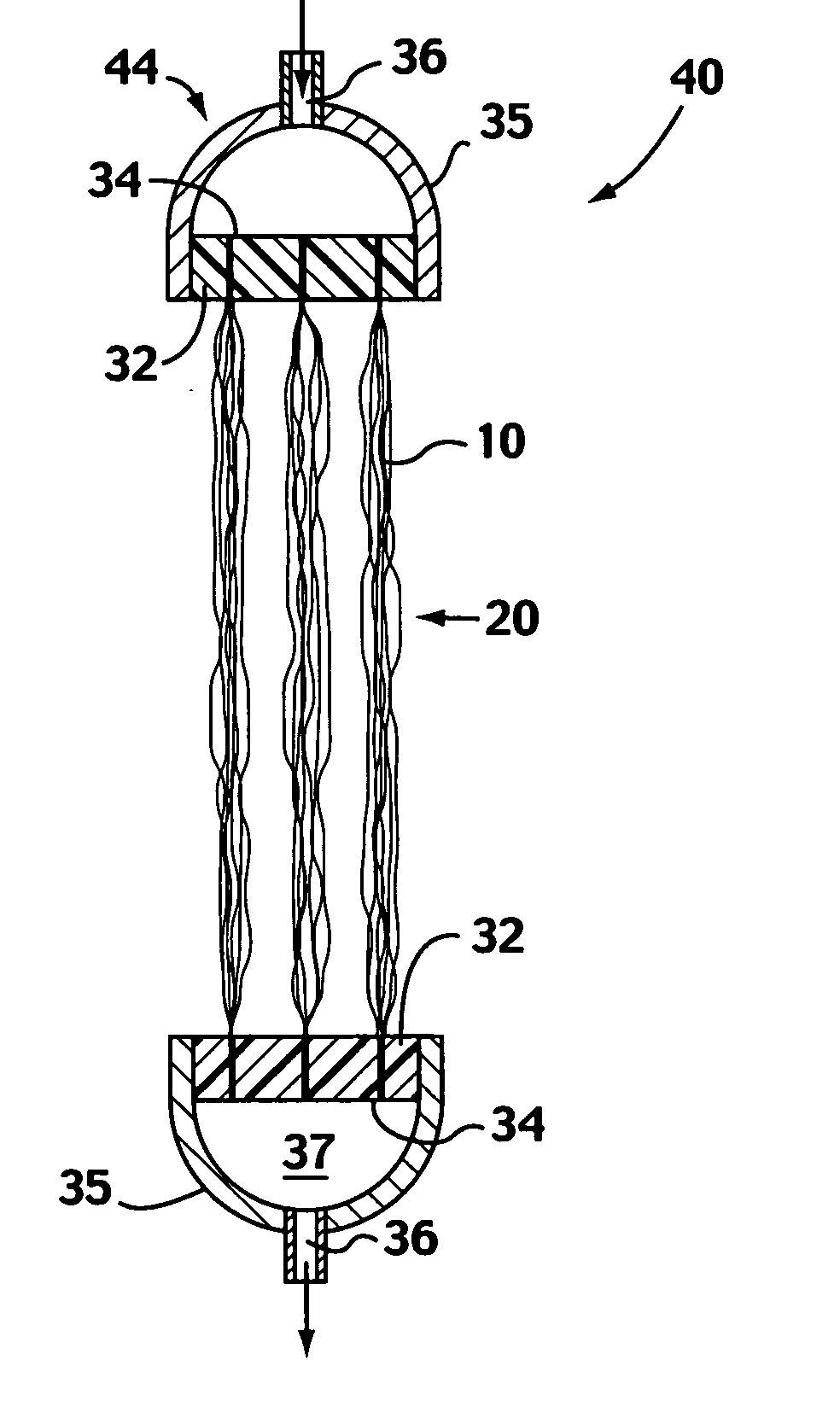
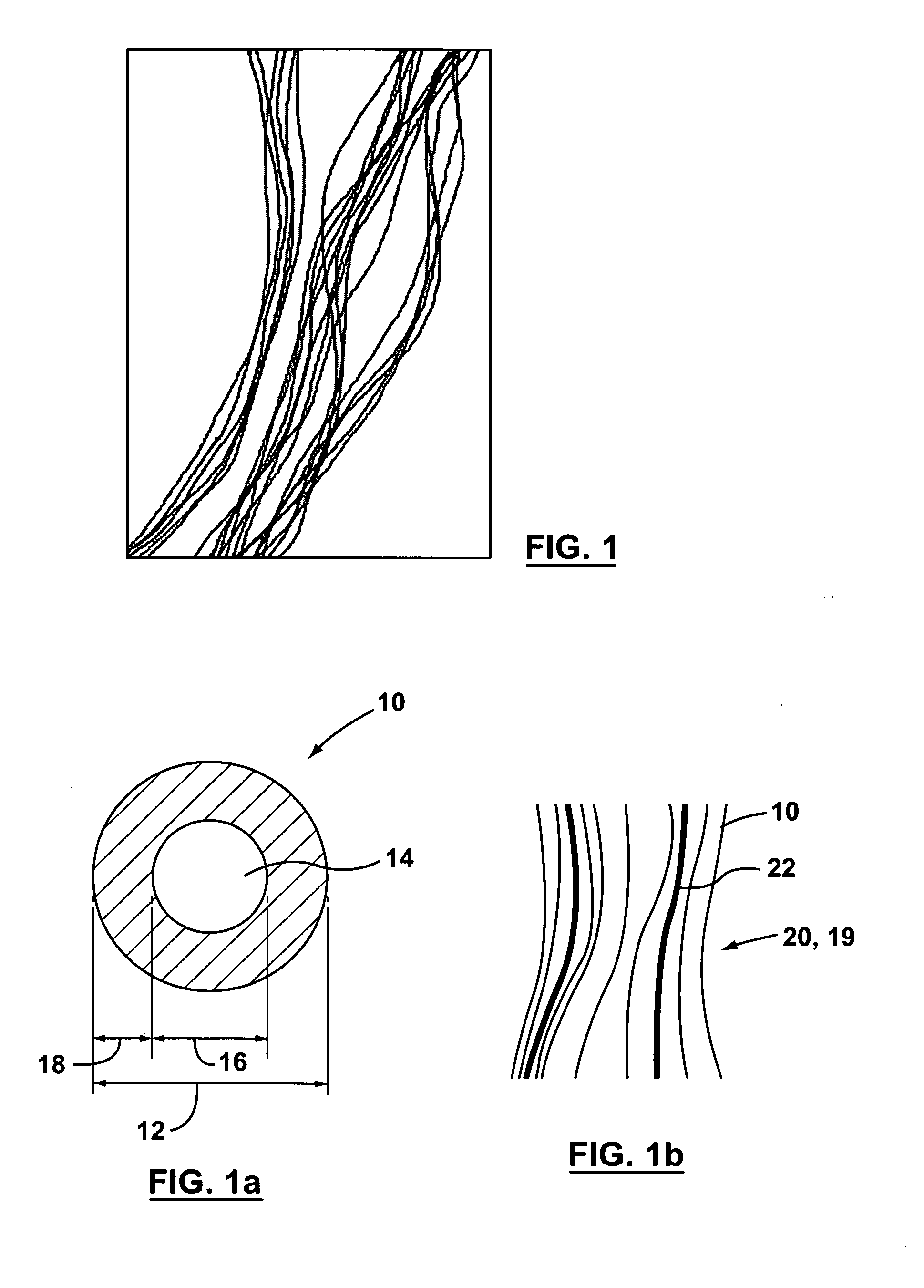
"The invention provides a membrane and module technology for treating water using membrane supported bioreactor technology. The membrane and module have a high gas transfer rate and surface area, allowing for the growth of a biofilm and the use of air as an oxygen source. The membrane and module can be made from non-porous materials such as poly methylpentene (PMP) or other thermoplastic polymers such as polyolefins. The invention also provides a fabric with a large number of hollow fibers for oxygen transfer and a module with high packing density for good substrate velocities. The invention provides a more cost-effective and efficient method for treating water using membrane supported bioreactor technology."

Problems solved by technology

However, PMP is still expensive compared to more common materials.
For example, it is currently about 10 times as expensive as other thermoplastic polymers including more common polyolefins such as polyethelene (PE) and polypropylene (PP).
However, the chemically treated pores tend to wet out in practice when immersed in water containing surfactants or proteins resulting in a significant decrease in flux rate.
This lack of selectivity may make the fibres unsuitable for gas separation but the inventors have found that high selectivity is not required, and may even be undesirable, in many water treatment applications.

Method used


Image

  • Supported biofilm apparatus and process
  • Supported biofilm apparatus and process
  • Supported biofilm apparatus and process

Examples


example 1

Chemical Oxygen Demand (COD) Reduction in a Membrane Supported Bioreactor

[0146] A bench scale bioreactor was made using a module generally as presented in FIGS. 6-9 except that only a single sheet of the fibres was used. The length of the sheet was 0.57 m and height 0.45 m, providing a total biofilm area of approximately 0.5 m2 assuming a with both sides of sheet available for biofilm growth. The ratio of surface area for gas transfer to surface area of attached biofilm was between about 5 and 6. Inlet air flow was 25 ml / min at a pressure of 34.5 kPa. Reactor volume was 30 L. Synthetic wastewater with a COD level of 1000 mg / l was introduced in a batch manner periodically. The synthetic wastewater consisted of 1.0 g / L of soluble peptone and 0.03 g / L of sodium hydrogen phosphate dissolved in tap water. A series of batch reactions were conducted to determine the rate of reaction and oxygen transfer efficiency. FIG. 21 presents the results of three batch periods: a three day period for...

example 2

Bench Test With Synthetic Wastewater

[0147] A bench scale bioreactor was designed using a single sheet module as described for Example 1. Synthetic wastewater with a COD level of 1000 mg / l, as described in Example 1, was introduced and treated by the biofilm on the module. Rates of COD removal and oxygen transfer and the thickness of the biofilm were calculated or measured and recorded. For about the first 21 days, the reactor (which has a 30 L fill volume) drained and re-filled with feed after variable batch periods to keep the CODs in the tank generally between 500 and 1000 mg / L. At day 8 and day 16, in addition to emptying the tank and re-filling it with new feed, the module was powerwashed with a water sprayer to remove biofilm. From about day 21 to day 30, the biofilm was subjected to starvation (i.e. the tank was filled with tap, i.e. clean or drinkable, water while oxygen supply continued to the module) and air scouring treatments. On about day 30, the tank was emptied and re...

example 3

Pilot Study With Industrial Wastewater

[0148] A small pilot study was conducted using four modules generally as shown in FIGS. 6 to 9. Each module has 6 sheets of fibers and a total planar surface area, or area of biofilm, of about 3.6 m2, and a ratio of surface area for gas transfer to surface area of attached biofilm of between about 5 and 6. The modules were installed in a 300 litre tank. The reactor was initially operated with peptone (about 2000 mg / l) and then peptone added to wastewater in a declining ration to accelerate the initial growth of biofilm on the sheets but then acclimatize the biofilm to the wastewater. After acclimatizing the biofilm, batch operations were conducted, filling the tank with industrial wastewater. The wastewater was drawn from multiple sources in ratios chosen to create an feed COD of about 3000 mg / l. “Pure” oxygen was supplied to the modules at a feed pressure of about 5 psi. As shown in FIG. 23, bulk CODs concentration dropped to less than 1000 mg...


PUM

PropertyMeasurementUnit
thicknessaaaaaaaaaa
thicknessaaaaaaaaaa
thicknessaaaaaaaaaa

Abstract

A membrane supported biofilm reactor uses modules having fine, hollow fibres, for example, made from melt spun thermoplastic polymers treated after spinning to increase their permeability to oxygen, used, for example, in tows or formed into a fabric. In one module, one or more sheets of the fabric are potted into a module to enable oxygen containing gas to be supplied to the lumens of the hollow fibres. Various reactors and processes, for example to treat wastewater, using such modules are described. In one process, oxygen travels through fibers, optionally through an attached biofilm, to oxygenate surrounding water. Mechanical, chemical and biological methods, for example endogenous respiration, are used to control the thickness of the biofilm.

Description

[0001] This is (1) a continuation of U.S. application Ser. No. 11 / 203,197 filed Aug. 15, 2005; which is a continuation-in-part of International Application No. PCT / CA2004 / 000206 filed Feb. 13, 2004 (2) a continuation of International Application No. PCT / CA2004 / 001495 filed Aug. 12, 2004; (3) a continuation-in-part of U.S. application Ser. No. 10 / 896,086 filed Jul. 22, 2004; (4) a continuation-in-part of U.S. Ser. No. 10 / 801,660 filed Mar. 17, 2004, which is an application claiming the benefit under 35 USC 119(e) of U.S. Provisional Patent Application Ser. No. 60 / 496,178 filed Aug. 18, 2003; (5) a continuation-in-part of U.S. Ser. No. 10 / 777,204 filed Feb. 13, 2004 which is an application claiming the benefit under 35 USC 119(e) of U.S. Provisional Patent Application Ser. No. 60 / 447,025 filed Feb. 13, 2003; (6) a continuation-in-part of International Application No. PCT / CA2004 / 001496 filed Aug. 12, 2004; and, (7) a continuation-in-part of Ser. No. 10 / 895,959 filed Jul. 22, 2004. This...

Claims


Application Information

Patent Timeline
Patent Type & Authority Applications(United States)
IPC IPC(8): C02F3/00
CPCB01D63/02B01D63/021B01D63/022B01D63/04B01D69/084B01F13/0266C02F3/102C02F3/103C02F3/208C02F3/30C02F3/302C02F2103/005C02F2103/008Y02W10/10B01F33/4062B01D63/034B01D63/0233
Inventor COTE, PIERRE LUCIENHUSAIN, HIDAYATBEHMANN, HENRY
Owner ZENON TECH PARTNERSHIP
Learn More