Engine control device

a technology of engine control and control device, which is applied in the direction of electrical control, marine propulsion, vessel construction, etc., can solve the problems of increasing cost and achieve the effect of preventing the occurrence of engine speed variation, cost increase, and more complicated and time-consuming maintenance procedures

Active Publication Date: 2006-07-20
MITSUBISHI ELECTRIC CORP +1
View PDF6 Cites 6 Cited by
  • Summary
  • Abstract
  • Description
  • Claims
  • Application Information

AI Technical Summary

Benefits of technology

[0009] An aspect of at least one of the embodiments disclosed herein includes the realization that, in the conventional watercraft noted above, in some cases, engine speed exceeds or does not reach a target speed during a throttle / steering assist operation, due to variations in the manufacture of the engine, variations in the operation of an actuator for opening and closing the throttle valve, or the like. For example, after prolonged use, a throttle valve or throttle valve shaft can become sticky, and thus will not move as fast as when the throttle valve was new. To solve such problems, strict predetermined settings, accuracy and the like in the associated mechanical designs can be used, however, such results in cost increases and more complicated and time-consuming maintenance procedures. On the other hand, adjustment of ignition timing during such operational modes can be used to compensate for the change in performance of the engine components, thereby preventing the occurrence of variation in engine speed by controlling ignition timing without cost increase and degraded maintainability.

Problems solved by technology

For example, after prolonged use, a throttle valve or throttle valve shaft can become sticky, and thus will not move as fast as when the throttle valve was new.
To solve such problems, strict predetermined settings, accuracy and the like in the associated mechanical designs can be used, however, such results in cost increases and more complicated and time-consuming maintenance procedures.

Method used


Image

  • Engine control device
  • Engine control device
  • Engine control device

Examples


Embodiment Construction

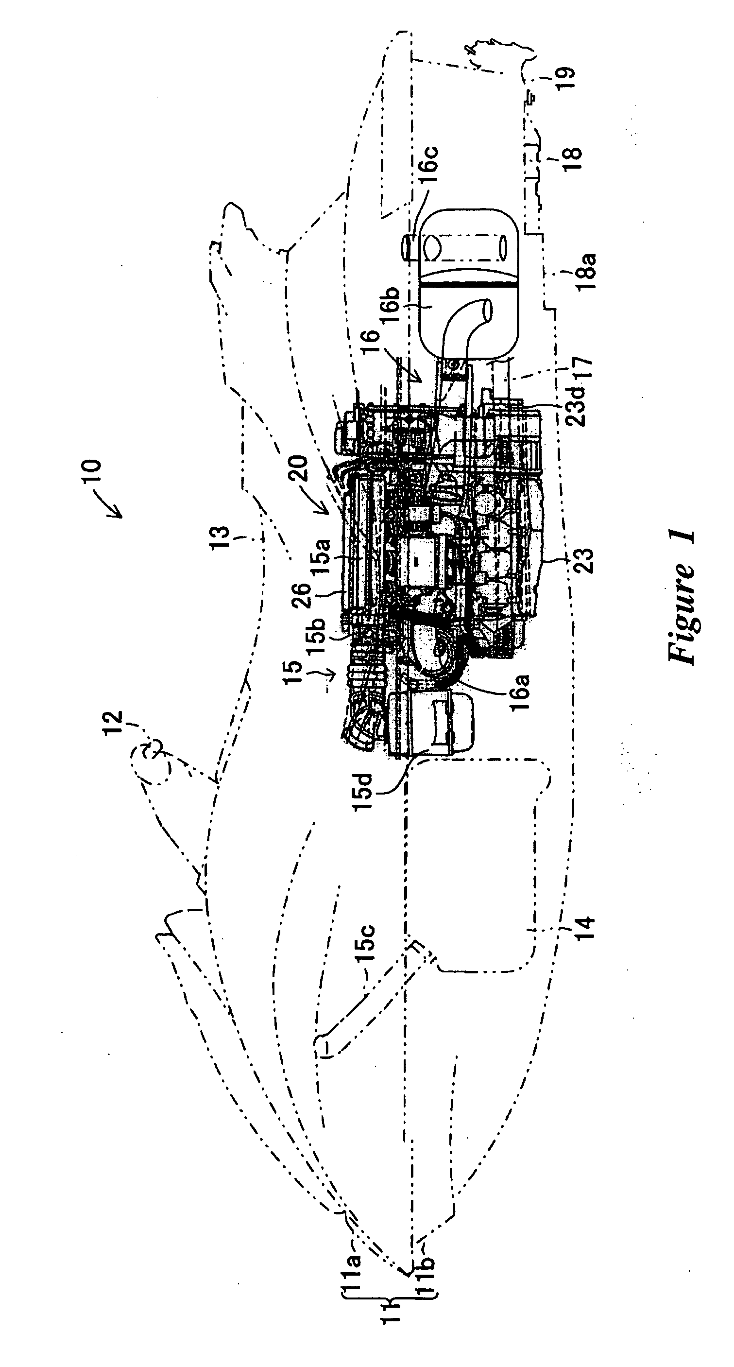
[0019] An embodiment is described below with reference to the drawings. FIG. 1 shows a personal water-jet propulsion watercraft 10 with an engine control device 20. The embodiments disclosed herein are described in the context of a personal watercraft because these embodiments have particular utility in this context. However, the embodiments and inventions herein can also be applied to other marine vessels, such as and small jet boats, as well as other vehicles.

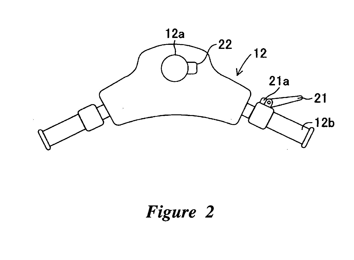
[0020] With reference to FIG. 1, in the boat 10, a boat body 11 is formed of a deck 11a and a lower hull 11b. A steering handle 12 is provided in the upper part of the boat body 11 at a portion, forwardly of the center. A seat 13 is provided in the upper part of the boat body 11 at about the middle of the boat 10. The steering handle 12, also shown in FIG. 2, is mounted to the upper end of a steering shaft 12a provided in the boat body 11, for rotation about or with the steering shaft 12a.

[0021] With reference to FIG. 2, in...


PUM


Abstract

An engine control device can include a throttle valve for adjusting an amount of air supplied to an engine, operation amount detecting sensors for detecting an operation amount of a throttle lever, a motor for driving the throttle valve between open and closed positions according to detection values of the operation amount detecting sensor 21a or the like, and throttle opening detecting sensors for detecting an opening of the throttle valve is provided with a limp-home mechanism for keeping the throttle valve in a mechanically neutral position when an abnormality occurs. When the throttle valve is in the mechanically neutral position, an ignition timing control can be switched in a stepwise manner over a predetermined time period from a regular ignition timing control to a limp-home ignition timing control.

Description

PRIORITY INFORMATION [0001] This application is based on and claims priority under 35 U.S.C. §119 to Japanese Patent Application No. 2005-007553, filed on Jan. 14, 2005, the entire contents of which is hereby expressly incorporated by reference herein. BACKGROUND OF THE INVENTION [0002] 1. Field of the Inventions [0003] The present inventions relate to an engine control device including ignition timing control functions. [0004] 2. Description of the Related Art [0005] Water jet propulsion boats, some of which are referred to as “personal watercraft” are provided with a throttle lever disposed in the vicinity of a grip of the steering handlebars. The engines of such watercraft propel the watercraft according to operation of the throttle lever. The heading of the watercraft is changed according to operation of the handlebars. [0006] Recently, several personal watercraft manufacturers have incorporated into such watercraft, systems which can raise engine output when an operator operate...

Claims


Application Information

Patent Timeline
Patent Type & Authority Applications(United States)
IPC IPC(8): B60K41/00B63H21/21
CPCB63H21/21B63H21/22F02D11/107F02D41/0205F02D41/22F02D2041/227F02D2200/0404F02D2200/602F02P5/1502Y02T10/46Y02T10/40
Inventor ISHIDA, YASUHIKOKINOSHITA, YOSHIMASA
Owner MITSUBISHI ELECTRIC CORP
Why Eureka
Try Eureka