Drive mechanism for a power tool
a technology of drive mechanism and power tool, which is applied in the direction of positive displacement liquid engine, portable drilling machine, liquid fuel engine, etc., can solve the problems of increasing the cost and manufacturing complexity of the drive mechanism, and achieve the effect of easy assembly of the drive mechanism
- Summary
- Abstract
- Description
- Claims
- Application Information
AI Technical Summary
Benefits of technology
Problems solved by technology
Method used
Image
Examples
second embodiment
[0079] A hammer drill of the invention is shown in FIGS. 9 and 10, with parts common to the embodiment of FIGS. 3 to 8 denoted by like reference numerals but increased by 100.
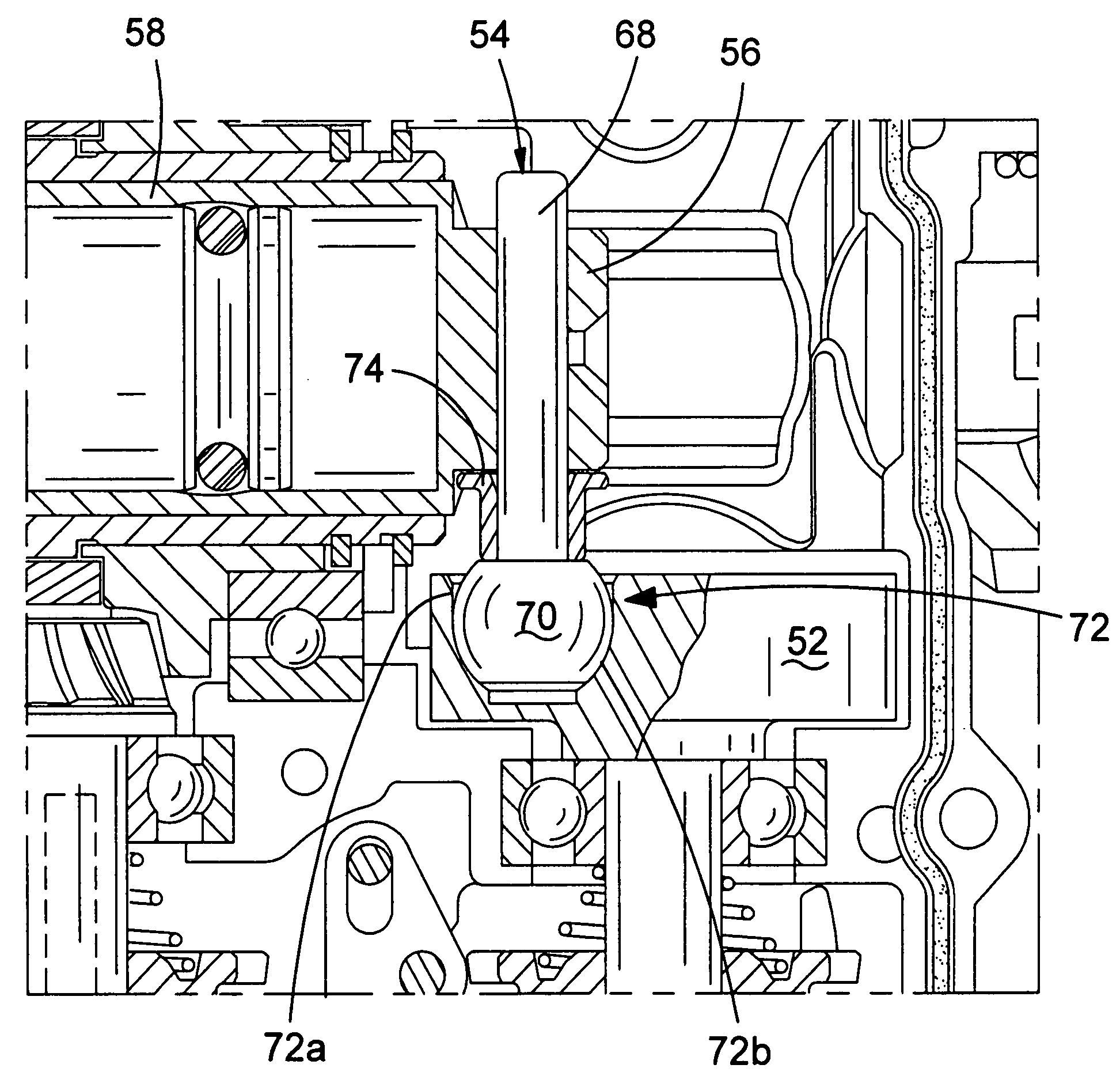
[0080] Crank pin 154 is of the same construction as the embodiment of FIGS. 3 to 8. However, in the embodiment of FIGS. 9 and 10 the collar member 176 is a coil spring. A washer 178 is provided between the collar coil spring 176 and the cylindrical bearing 156. The collar coil spring 176 has the further advantage of biasing the part-spherical bearing 170 of the crank pin 154 into engagement with the cup-shaped recess 172 of the crank plate 152 so that the part-spherical bearing is prevented from even partially moving out of engagement with the crank plate 152.
third embodiment
[0081] A hammer drill of the invention is shown in FIGS. 11 to 13, with parts common to the embodiment of FIGS. 3 to 8 denoted by like reference numerals but increased by 200.
[0082] The transmission housing 280 is formed from two clamshell halves of durable plastics or cast metal material. The two clamshell halves trap and compress an O-ring 282 therebetween. The transmission housing 280 is supported by first and second damping springs 284 and 286 at its rearward end. The transmission housing 280 is also mounted on parallel rails (not shown) disposed within the tool housing 222 such that the transmission housing 280 can slide a small distance relative to the tool housing 222 backwards and forwards in the direction of the longitudinal axis of the spindle 248.
[0083] The spring coefficients of damping springs 284 and 286 are chosen so that the transmission housing 280 slides to a point generally mid-way between its limits of forward and backward travel when the hammer drill is used in...
fourth embodiment
[0085] A hammer drill of the invention is shown in FIG. 14, with parts common to the embodiment of FIGS. 3 to 8 denoted by like reference numerals but increased by 300.
[0086] The hammer drill 320 has a tool housing 322. In this embodiment, the transmission housing 380 is formed from three housing portions. A generally L-shaped first housing portion 380a accommodates the transmission mechanism except for the first and second gears 340, 342 and the front end 348a of the spindle 348. The bottom end of the first housing portion 380a is mounted upon a second housing portion 380b such that a first O-ring 382a is trapped between the two portions to prevent the ingress of dust and dirt. The second housing portion 380b holds the lower parts of the transmission mechanism inside the first housing portion 380a and accommodates the first and second gears 340, 342. The second housing portion 380b has a motor output aperture 390 to allow the motor output shaft 336 access to the inside of the trans...
PUM
| Property | Measurement | Unit |
|---|---|---|
| angle | aaaaa | aaaaa |
| rotation | aaaaa | aaaaa |
| diameter | aaaaa | aaaaa |
Abstract
Description
Claims
Application Information
 - R&D
- Intellectual Property
- Life Sciences
- Materials
- Tech Scout
- Unparalleled Data Quality
- Higher Quality Content
- 60% Fewer Hallucinations
Browse by: Latest US Patents, China's latest patents, Technical Efficacy Thesaurus, Application Domain, Technology Topic, Popular Technical Reports.
© 2025 PatSnap. All rights reserved.Legal|Privacy policy|Modern Slavery Act Transparency Statement|Sitemap|About US| Contact US: help@patsnap.com


