Eureka AIR delivers breakthrough ideas for toughest innovation challenges, trusted by R&D personnel around the world.

Linear guide device and rolling element accommodating belt for the same

a technology of linear guide and accommodating belt, which is applied in the direction of linear bearings, shafts and bearings, bearings, etc., can solve the problems of increasing noise intensity, early abraded rolling elements, and inability of rolling elements to roll smoothly, so as to prevent excessive force

Active Publication Date: 2006-07-20
NSK LTD
View PDF1 Cites 23 Cited by
  • Summary
  • Abstract
  • Description
  • Claims
  • Application Information

AI Technical Summary

Benefits of technology

[0025] One or more embodiments of the invention provide a rolling element accommodating belt for a linear guide device in which a rolling element can be easily incorporated into the rolling element accommodating belt, and a connecting member of the rolling element accommodating belt can be prevented from wearing, and a linear guide device provided with the rolling element accommodating belt.
[0026] One or more embodiments of the invention provide a linear guide device capable of reducing vibration and noise at the time of operation.
[0027] One or more embodiments of the invention provide a linear guide device and a rolling element accommodating belt used for the linear guide device capable of preventing a connecting member of the rolling element accommodating belt from being repeatedly given an excessively strong tensile force.

Problems solved by technology

Accordingly, it is impossible for the rolling elements to roll smoothly.
Therefore, an intensity of noise is increased and the rolling elements are early abraded.
This assembling work takes time and labor.
However, in the case where each rolling element is accommodated in each rolling element accommodating section by means of insertion forming at the time of forming the rolling element accommodating belt, the following problems may be encountered.
As described in Patent Document 3, in order to give a rotating property to the rolling element (ball), it is takes a very long period of time, and further it is difficult to give a smooth rotating property to the rolling element (ball).
In some cases, it is impossible to give a rotating property to the rolling element (ball) according to the type of resin.
Consequently, the connecting member of the rolling element accommodating belt is strongly rubbed with the guide section, which might damage the connecting member.
For example, as described in Patent Document 6, existence of the end portions of the rolling element accommodating belt, which is formed being provided with end portions, can be a cause of obstructing the smooth operation of the linear guide device.
In this connection, Patent Document described above discloses a technique of reducing an increase in the circulating resistance described above, however, as long as the end portion itself is existing, it is difficult to completely eliminate the generation of the circulating resistance.
Accordingly, vibration and noise are more increased at the time of operation.
Therefore, when the phases of the infinite circulating passages coincide with each other in the aligning direction, a smooth operation of the linear guide device is obstructed.
Therefore, the problem caused by vibration and noise, which are generated at the time of operation, can not be solved.

Method used


Image

  • Linear guide device and rolling element accommodating belt for the same
  • Linear guide device and rolling element accommodating belt for the same
  • Linear guide device and rolling element accommodating belt for the same

Examples


first embodiment

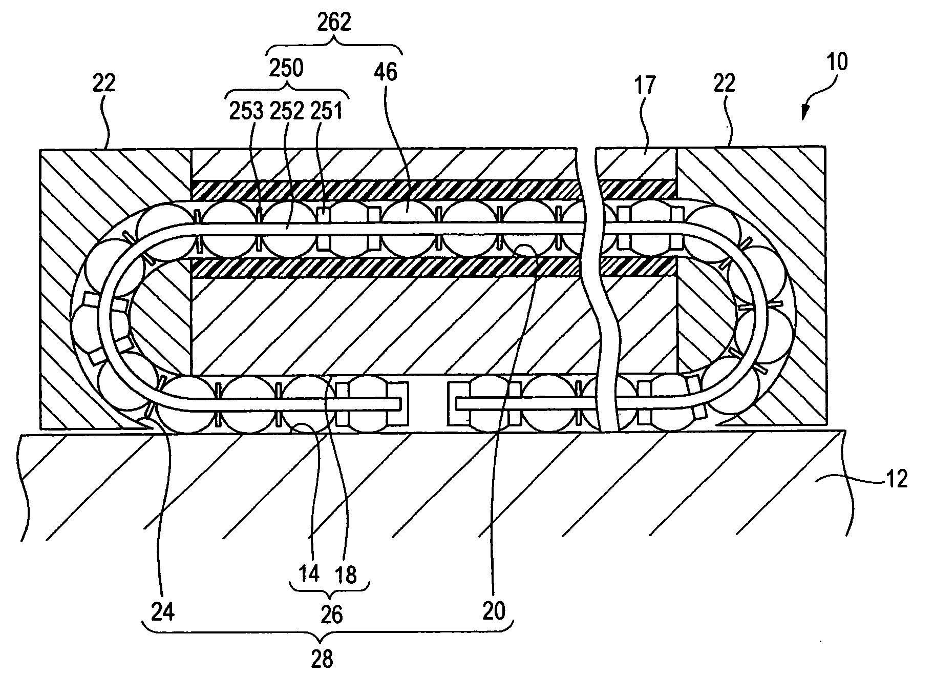
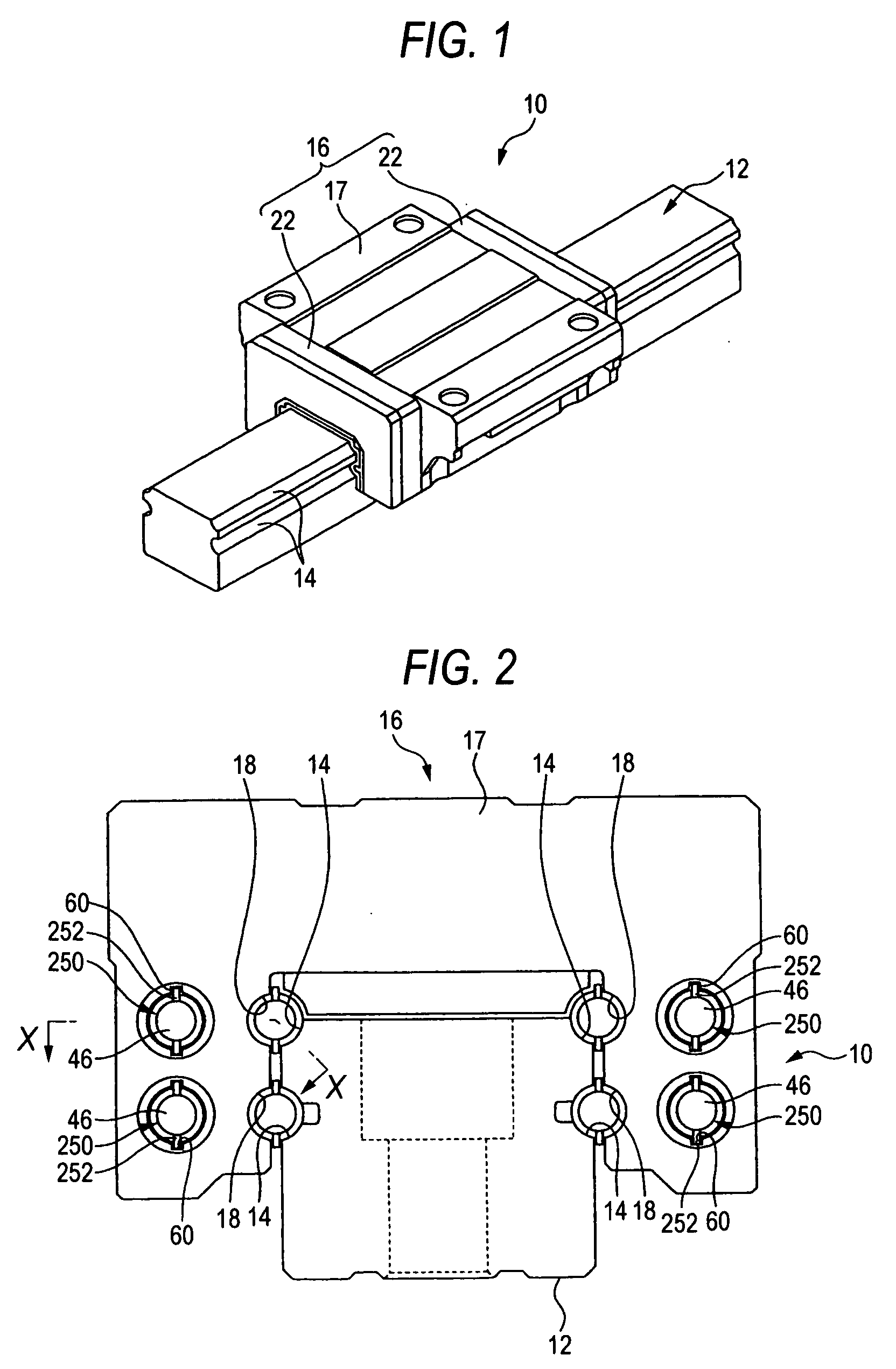
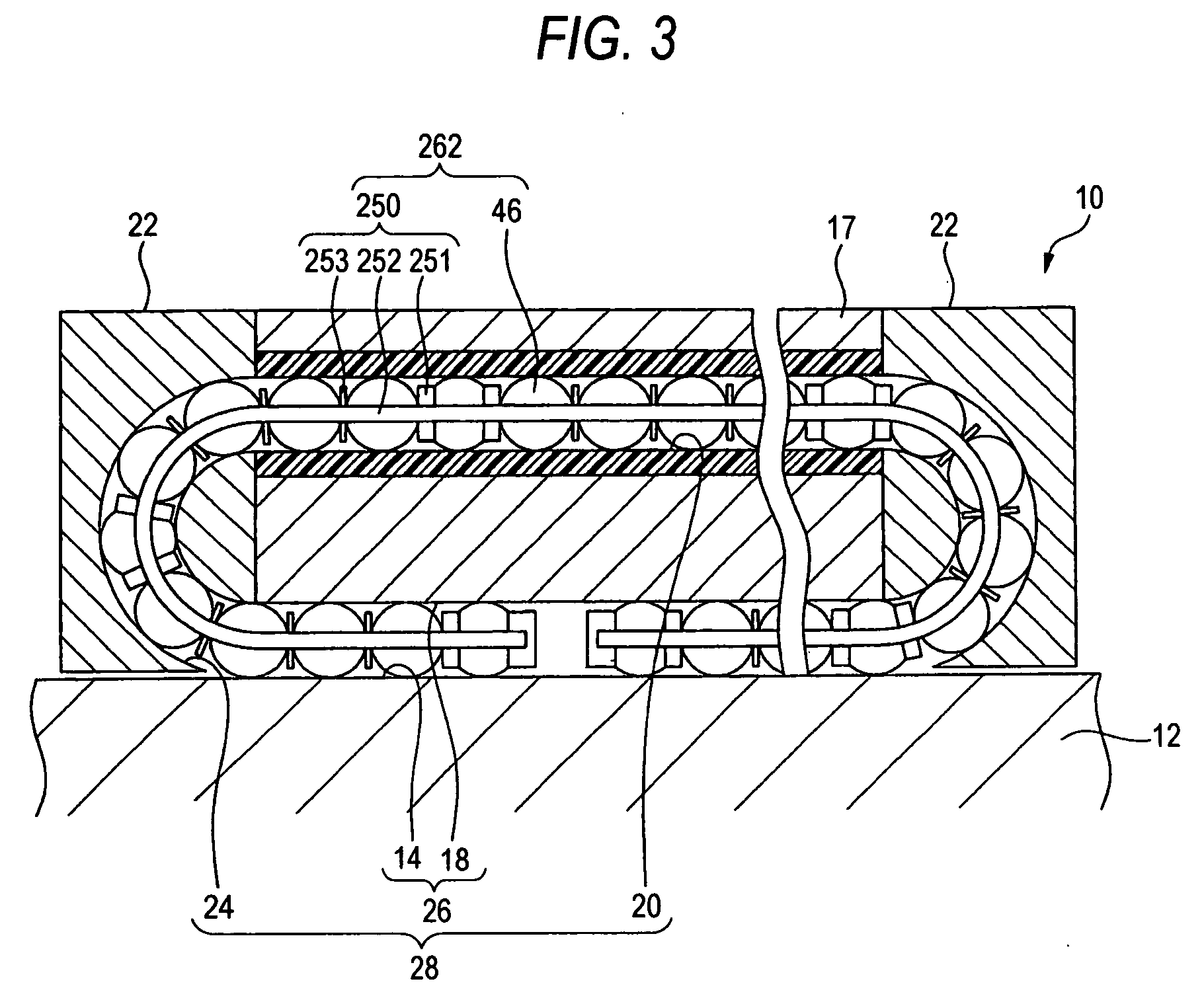
[0095]FIG. 1 is a perspective view showing a linear guide relating to the linear guide device into which the rolling element accommodating belt of the present invention is incorporated. FIG. 2 is a front view of the linear guide shown in FIG. 1, wherein an end cap is removed from the linear guide. FIG. 3 is a sectional view of the linear guide taken on line X-X in FIG. 2.

[0096] As shown in FIGS. 1 and 2, this linear guide 10 includes: a guide rail 12 having a rolling element guide face 14; and a slider 16 slidably arranged on the guide rail 12 being capable of moving relatively with respect to the guide rail 12.

[0097] The guide rail 12 has a substantially square cross section, and two linear rolling element guide faces 14 are formed on each side of the guide rail 12 in the longitudinal direction, that is, in total, four linear rolling element guide faces 14 are formed on both sides of the guide rail 12 in the longitudinal direction.

[0098] As shown in FIG. 1, the slider 16 includes...

second embodiment

[0128] As shown in FIGS. 9(d) and 9(e), the no-restraint accommodating section B is composed in such a manner that the directions of the substantially U-shaped opening portions of the spacer members 81 are set to be the same with each other. Therefore, the ball 46 is allowed to come off on the opening side of the substantially U-shaped opening portions of the spacer members 81. Especially in the rolling element accommodating belt 80 of this second embodiment, the azimuth, in which the ball 46 is allowed to come off, is set only on the opening side in the developed shape, that is, the azimuth, in which the ball 46 is allowed to come off, is set only in the same azimuth.

[0129] Concerning the arrangement of the restraint accommodating section A and the no-restraint accommodating section B, both end portions of the rolling element accommodating belt 80 are composed of the restraint accommodating sections A in the same manner as that of the first embodiment described before. As shown in ...

fourth embodiment

[0143] In the fourth embodiment shown in FIGS. 11(g) and 11(h), each spacer member 84 is composed of a substantially rectangular pawl portion which protrudes in the direction of both sides of the connecting member 252. This pawl portion is composed of a curved face 84a opposing to the ball accommodating hole 255. The ball 46 is allowed to rotate between the curved faces 84a opposing to each other. Further, these curved faces 84a opposing to each other compose the restraint accommodating portion A capable of restraining the ball 46 so that it can not come off.

[0144] In the fifth variation shown in FIGS. 11(i) and 11(j), the spacer member 85 is composed of one pawl portion, the shape of which is a substantial rectangle, protruding to one side of the direction of both sides of the connecting member 252 and also composed of the other pawl portion, the shape of which is a substantial rectangle, protruding to the opposite side of the pawl portion. Each pawl portion has a curved face 85a d...


PUM


Abstract

In a rolling element accommodating belt having a rolling element accommodating section for individually accommodating a plurality of balls at predetermined intervals while the plurality of balls are rolling and circulating in an infinite circulating passage of linear guide, the rolling element accommodating belt accommodates the balls in the rolling element accommodating section and aligns the balls in the direction of aligning balls in the infinite circulating passage. The rolling element accommodating section includes: a restraint accommodating section for restricting the accommodated balls in all directions; and a no-restraint accommodating section in which the accommodated balls are not restrained at least in one direction.

Description

[0001] The present application claims foreign priorities based on Japanese Patent Application No. 2004-328095, filed Nov. 11, 2004, Japanese Patent Application No. 2005-021214, filed Jan. 28, 2005 and Japanese Patent Application No. 2005-120899, filed Apr. 19, 2005, the contents of which are incorporated herein by reference. BACKGROUND OF THE INVENTION [0002] 1. Technical Field [0003] The present invention relates to a linear guide device and a rolling element accommodating belt for the linear guide device. [0004] 2. Related Art [0005] A linear guide device having a plurality of rows of infinite circulating passages includes: as shown in FIG. 29, a guide rail 12; a slider 16 arranged being capable of moving relatively with this guide rail 12; and a plurality of rolling elements 46 (in this example, balls) which roll between the guide rail 12 and the slider 16 under a load. The guide rail 12 has a rolling element guide face 14 on which the rolling elements 46 roll. The slider 16 incl...

Claims


Application Information

Patent Timeline
IPC IPC(8): F16C29/06
CPCF16C29/0609F16C29/0647F16C33/3825F16C43/06
Inventor MATSUMOTO, JUN
Owner NSK LTD
Why Eureka
Eureka Blog
Learn More