
Engine system and vehicle

Inactive Publication Date: 2006-07-20
YAMAHA MOTOR CO LTD
View PDF2 Cites 7 Cited by
  • Summary
  • Abstract
  • Description
  • Claims
  • Application Information

AI Technical Summary

Benefits of technology

[0012] In order to overcome the problems described above, preferred embodiments of the present invention provide an engine system allowing the engine speed of an engine to be prevented from fluctuating and a vehicle including the engine system without the necessity of complicating the structure of the engine. (1)

Problems solved by technology

This complicates the structure of the valve driving device.
Consequently, the air-fuel ratio is liable to change, and the engine speed of the engine is likely to fluctuate accordingly.
This complicates the structure of the engine.

Method used


Image

  • Engine system and vehicle
  • Engine system and vehicle
  • Engine system and vehicle

Examples


Embodiment Construction

[0057] Now, preferred embodiments of the invention will be described with reference to the accompanying drawings. Note that in the following description of the preferred embodiments, a motorcycle will be described as an example of a vehicle according to the invention.

[0058] (1) Structure of Engine

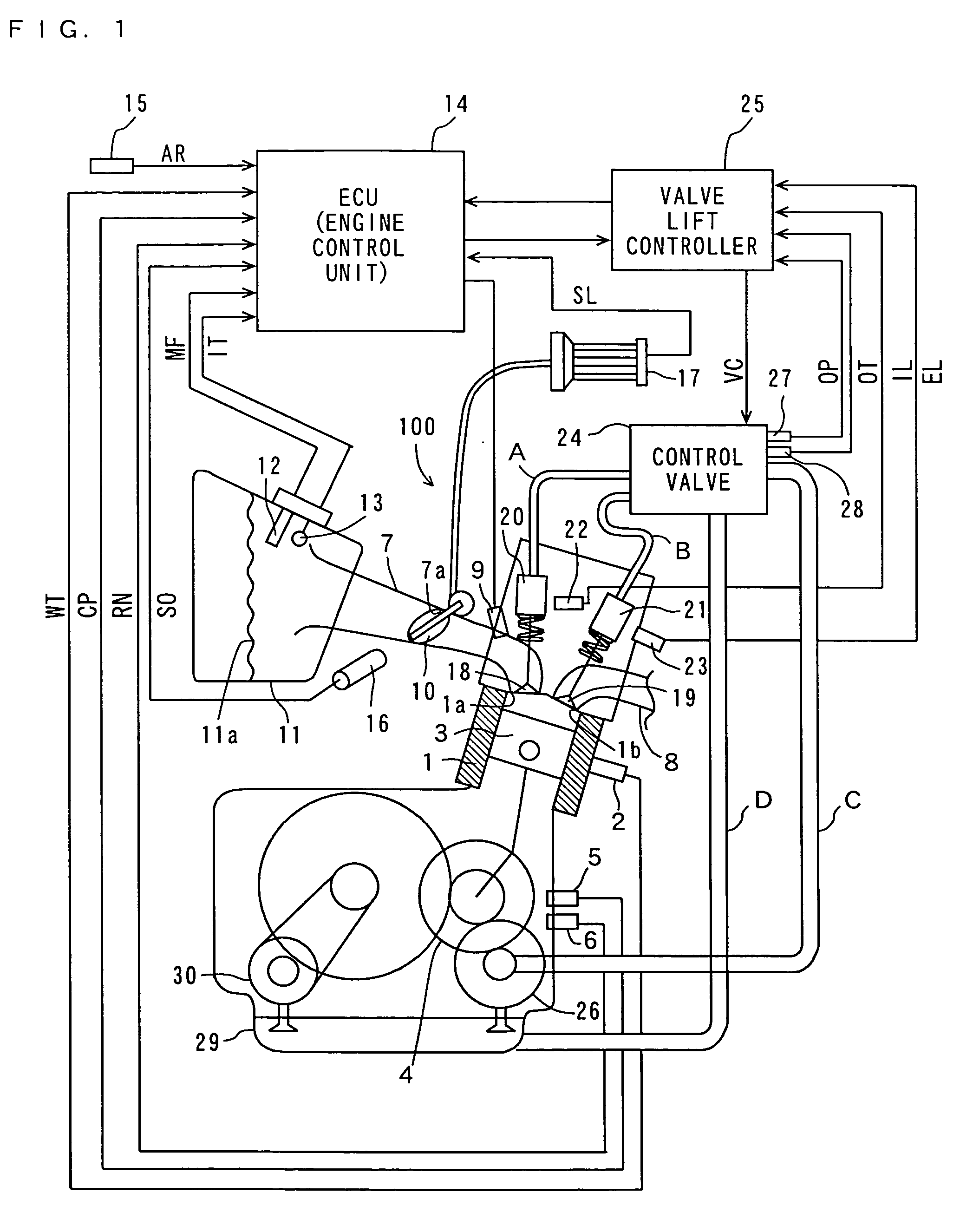
[0059]FIG. 1 is a schematic view illustrating an engine system including a hydraulic valve driving device according to a preferred embodiment of the invention.

[0060] The engine system in FIG. 1 includes an engine 100 and an engine control unit (ECU) 14. The engine 100 includes a water temperature sensor 2 provided in the vicinity of a side surface of a cylinder 1 to measure water temperature in the engine 100. A piston 3 provided in the cylinder 1 can reciprocate therein. A crank 4 that drives the piston 3 is provided under the piston 3. On a side of the crank 4, a crank angle sensor 5 and a rotation number sensor 6 are provided to detect the angle and the rotation number of the crank 4,...


PUM


Abstract

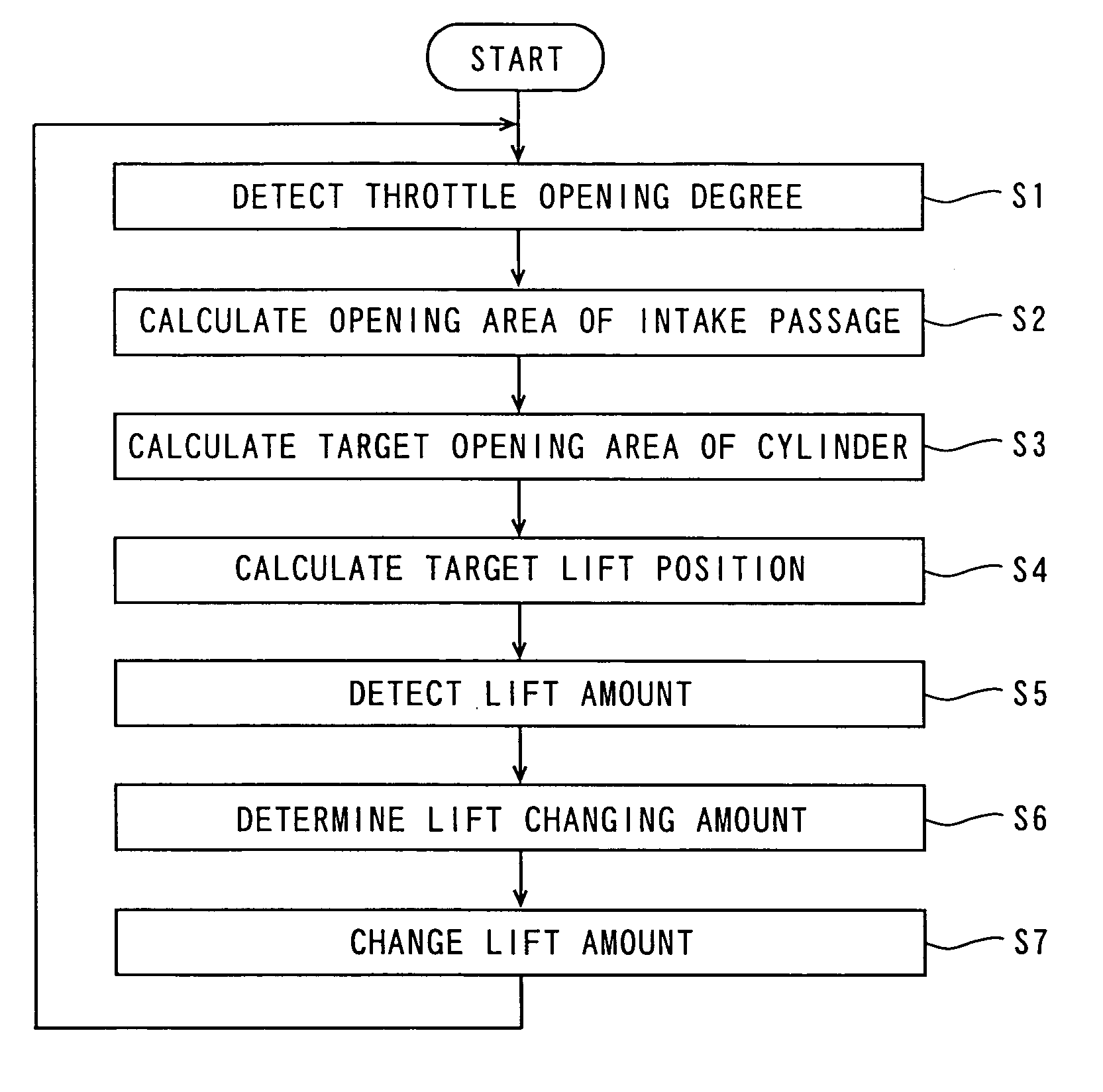
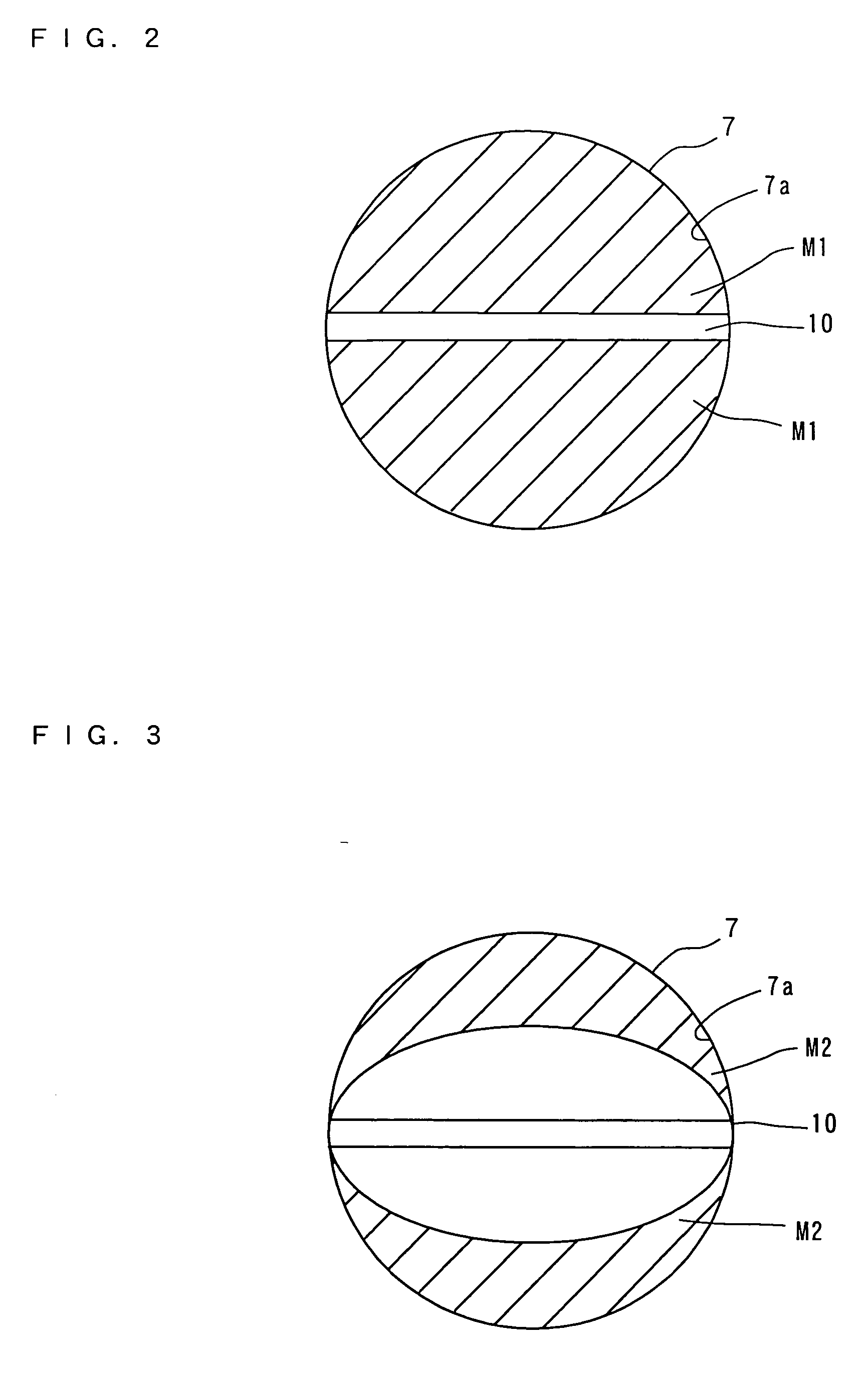
An engine system includes an engine and an engine control unit. The engine includes an intake valve that opens and closes the opening of a cylinder, a valve actuator that drives the intake valve and can arbitrarily control the lift amount of the intake valve, an intake passage that introduces air and fuel into the cylinder through the opening of the cylinder, and a throttle valve provided to open and close the opening of the intake passage and control the quantity of air to be introduced into the cylinder in response to a load required by a driver. During intake operation in substantially all the load states of the engine, the valve actuator is controlled so that the opening area of the opening determined by the lift amount of the intake valve is not less than the opening area of the opening determined by the opening degree of the throttle valve.

Description

BACKGROUND OF THE INVENTION [0001] 1. Field of the Invention [0002] The present invention relates to an engine system and a vehicle including the same, and more particularly to an engine system including a valve driving device that drives an intake valve and a vehicle including the engine system. [0003] 2. Description of the Background Art [0004] There have been conventionally known valve driving devices operable to drive an intake valve in an engine such as a mechanical valve driving device including a lift variable mechanism that changes the lift amount of an intake valve, and a hydraulic valve driving device operable to control the lift amount of an intake valve at an arbitrary level by oil pressure. [0005] In a conventional mechanical valve driving device including a lift variable mechanism, when the lift amount of the intake valve changes, the valve timing changes accordingly. Therefore, in order to achieve the optimum lift amount and the optimum valve timing at the same time, ...

Claims


Application Information

Patent Timeline
IPC IPC(8): F02D13/00
CPCF02B61/02F02D9/02F02D13/0207F02D13/0226F02D13/0253F02D41/0002F02D2041/002Y02T10/42Y02T10/18Y02T10/12Y02T10/40
Inventor TOMII, EIJI
Owner YAMAHA MOTOR CO LTD
Learn More