
Active vibration attenuation for implantable microphone

Active Publication Date: 2006-07-13
COCHLEAR LIMITED
View PDF71 Cites 60 Cited by
  • Summary
  • Abstract
  • Description
  • Claims
  • Application Information

AI Technical Summary

Benefits of technology

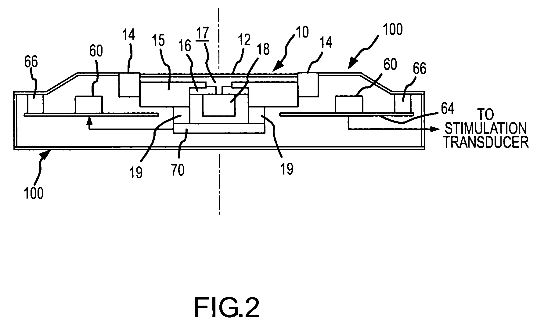
[0012] In either arrangement, the motion sensor(s) may be positioned such that an axis of sensitivity of the sensor is aligned with a principal direction of movement of the microphone diaphragm. Such a principal direction of movement may be substantially normal to a surface (e.g., a planar surface) defined by the diaphragm. Such alignment of the motion sensor may allow for enhanced detection of undesired movement between the diaphragm and overlying tissue (e.g., skin). More preferably, such an axis of sensitivity may extend through the center of mass of the microphone. This may allow for more accurately identifying movement of the microphone as an assembly. Accordingly, the center of mass of the microphone assembly and motion sensor(s) may be located on a common axis that may also be directed normal to the principal direction of movement of the microphone diaphragm. In an arrangement where a plurality of motion sensor(s) is employed, the sensors may be positioned so that their centroid or combinative center of mass is located on such a common axis.
[0031] Accordingly, the utility is operative to select between and / or blend the outputs of the first and second control loops based on current operating conditions in order to reduce noise perceived by a user of the implantable hearing system. In one arrangement, the utility is operative to select the control loop signal having a lower magnitude and hence the lower noise component. In further arrangements, such as sub-band processing arrangements, different control loops may be utilized for different frequency ranges. In this regard, the control loop that provides the best noise cancellation for a predetermined frequency range may be utilized.

Problems solved by technology

For a wearer a hearing instrument including an implanted microphone (e.g., middle ear transducer or cochlear implant stimulation systems), the skin and tissue covering the microphone diaphragm may increase the vibration sensitivity of the instrument to the point where body sounds (e.g., chewing) and the wearer's own voice, conveyed via bone conduction, may saturate internal amplifier stages and thus lead to distortion.
Certain proposed methods intended to mitigate vibration sensitivity may potentially also have an undesired effect on sensitivity to airborne sound as conducted through the skin.

Method used


Image

  • Active vibration attenuation for implantable microphone
  • Active vibration attenuation for implantable microphone
  • Active vibration attenuation for implantable microphone

Examples


Embodiment Construction

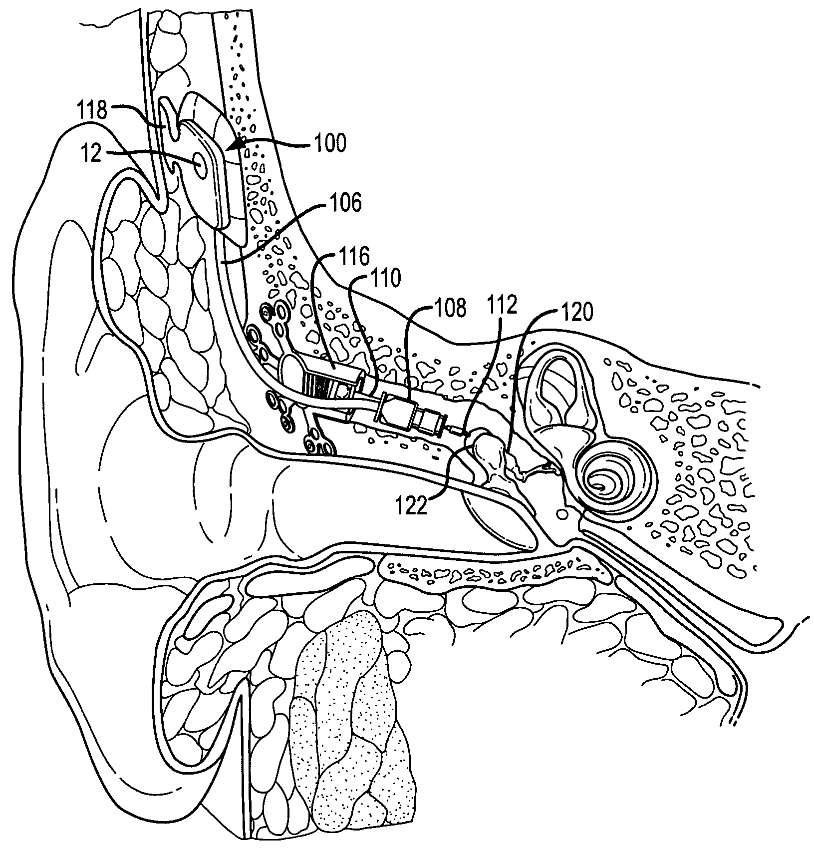
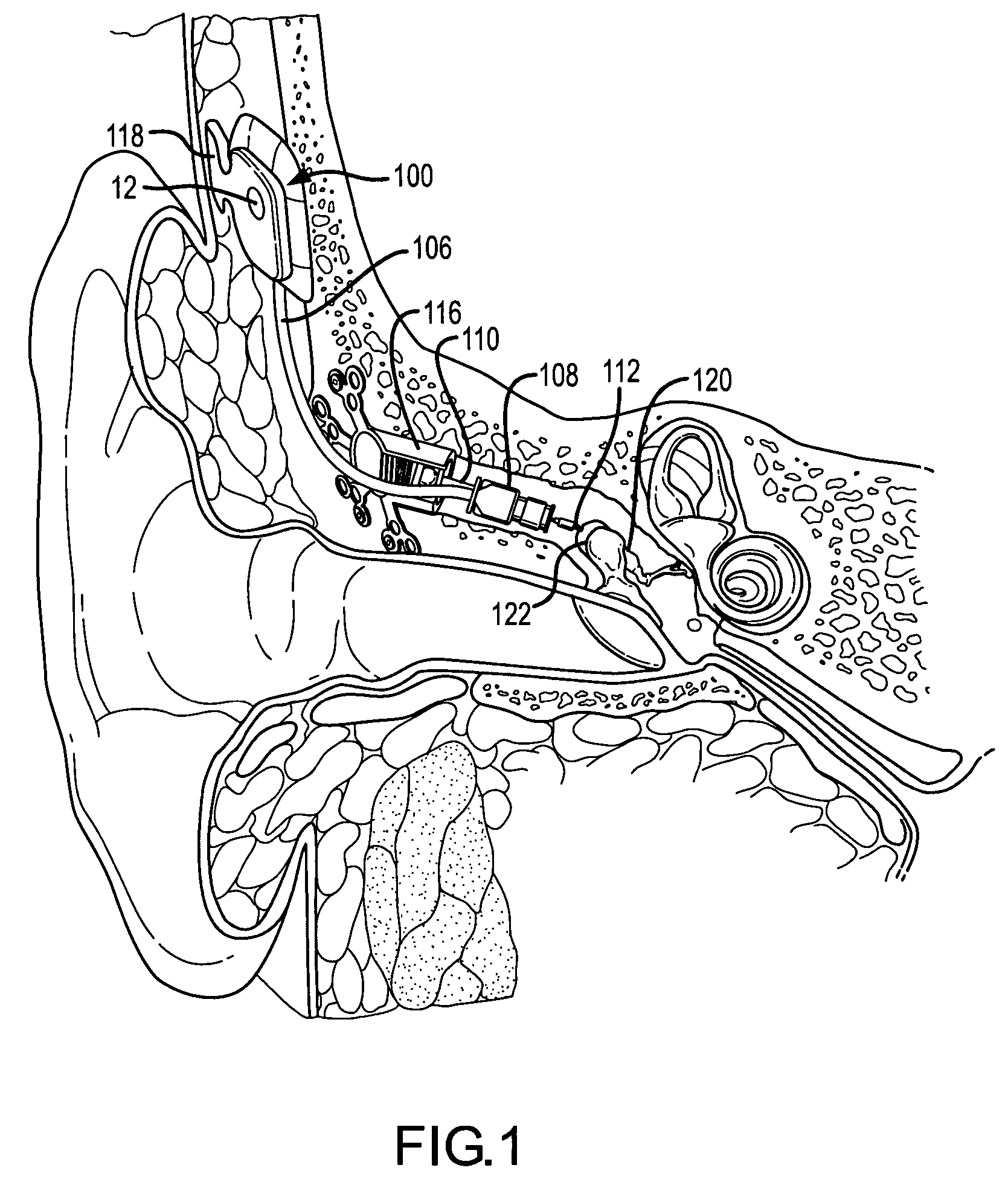
[0046] Reference will now be made to the accompanying drawings, which at least assist in illustrating the various pertinent features of the present invention. In this regard, the following description of a hearing instrument is presented for purposes of illustration and description. Furthermore, the description is not intended to limit the invention to the form disclosed herein. Consequently, variations and modifications commensurate with the following teachings, and skill and knowledge of the relevant art, are within the scope of the present invention. The embodiments described herein are further intended to explain the best modes known of practicing the invention and to enable others skilled in the art to utilize the invention in such, or other embodiments and with various modifications required by the particular application(s) or use(s) of the present invention.

[0047]FIG. 1 illustrates one application of the present invention. As illustrated, the application comprises a fully im...


PUM


Abstract

The invention is directed to an implanted microphone having reduced sensitivity to vibration. In this regard, the microphone differentiates between the desirable and undesirable vibration by utilizing at least one motion sensor to produce a motion signal when an implanted microphone is in motion. This motion signal is used to yield a microphone output signal that is less vibration sensitive. In a first arrangement, the motion signal may be processed with an output of the implantable microphone transducer to provide an audio signal that is less vibration-sensitive than the microphone output alone. Specifically, the motion signal may be scaled to match the motion component of the microphone output such that upon removal of the motion signal from the microphone output, the remaining signal is an acoustic signal.

Description

CROSS REFERENCE TO RELATED APPLICATIONS [0001] This application claims priority under 35 U.S.C. §119 to U.S. Provisional application 60 / 643,074 entitled “Active Vibration Attenuation For implantable Microphone” having a filing date of Jan. 11, 2005 and to U.S. Provisional Application U.S. Provisional 60 / 740,710 entitled “Active Vibration Attenuation For implantable Microphone” having a filing date of Nov. 30, 2005.FIELD OF THE INVENTION [0002] The present invention relates to implanted hearing instruments, and more particularly, to the reduction of undesired signals from an output of an implanted microphone. BACKGROUND OF THE INVENTION [0003] In the class of hearing aid systems generally referred to as implantable hearing instruments, some or all of various hearing augmentation componentry is positioned subcutaneously on, within, or proximate to a patient's skull, typically at locations proximate the mastoid process. In this regard, implantable hearing instruments may be generally d...

Claims


Application Information

Patent Timeline
IPC IPC(8): A61N1/08
CPCH04R19/016H04R25/606H04R2225/67
Inventor MILLER, SCOTT ALLAN III
Owner COCHLEAR LIMITED
Learn More