Eureka AIR delivers breakthrough ideas for toughest innovation challenges, trusted by R&D personnel around the world.

Illumination apparatus for oral cavity

a technology of oral cavity and illumination device, which is applied in the field of illumination apparatus, can solve the problems of insufficient opening of the mouth of patients, inability to use the oral expander in sufficient quantities, and inability to provide illumination devices to the oral expander,

Inactive Publication Date: 2006-07-13
YANG CHIEN HSIN
View PDF9 Cites 40 Cited by
  • Summary
  • Abstract
  • Description
  • Claims
  • Application Information

AI Technical Summary

Benefits of technology

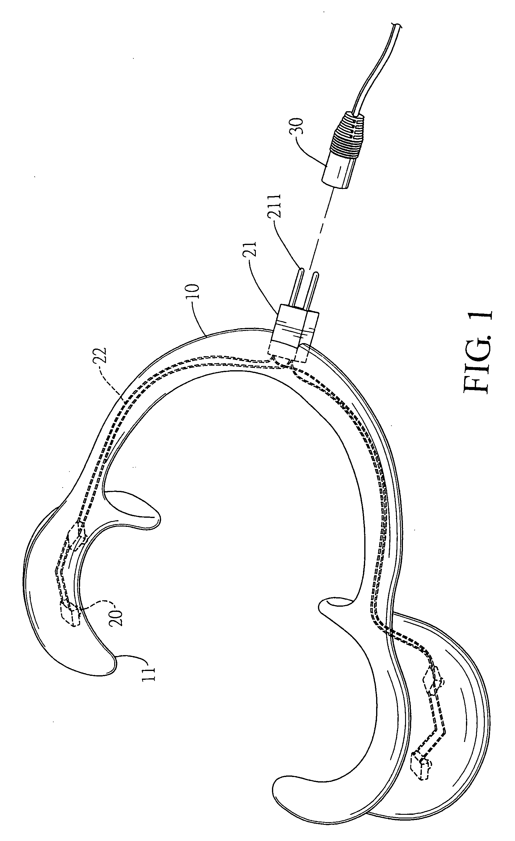
"The present invention provides an illumination apparatus for oral cavity that can be fixedly attached to an oral expander. The apparatus has a U-shaped sheet with arcuate braces that can be placed at the corners of the mouth to expand it and force the oral cavity to open. The sheet has illumination devices on at least one side of each arcuate brace, which can provide proper illumination on the patient's oral cavity for better treatment. This apparatus can ensure sufficient illumination even if the dentist's position blocks the lights from the upper portion of the mouth."

Problems solved by technology

However, some patients cannot open their mouths sufficiently during the course of treatment.
However, when adjusting the position, the dentist often blocks the light that illuminates the patient's oral cavity, and the treatment of the patient is influenced.
Although the dentist uses an oral expander for facilitating the treatment of some patients, yet the oral expander does not have any illumination device provided thereon.
Therefore, the oral expander substantially has no practicability with regard to the illumination on the patient's oral cavity.

Method used


Image

  • Illumination apparatus for oral cavity
  • Illumination apparatus for oral cavity
  • Illumination apparatus for oral cavity

Examples


first embodiment

[0016] An illumination apparatus for illuminating a patient's oral cavity according to the present invention is depicted in FIGS. 1 and 2. The illumination apparatus broadly includes a generally U-shaped sheet 10 having arcuate braces 11 defined at each of the two free ends thereof. Illumination devices 20 are operably coupled on one side of each arcuate brace 11. An electric connecter 21 is operably coupled with the illumination devices 20 via wires 22 at the closed end of the generally U-shaped sheet 10. In this embodiment, the illumination devices 20 comprise a plurality of light emitting diode (“LED”) light sources and the electric connecter 21 has outwardly protruding pins 211.

[0017] In use, as generally depicted in FIG. 3, an electric plug 30 can be coupled with the electric connecter 21 with the pins 211 inserted into electric plug 30. The other end of the electric plug 30 can be operably coupled with a battery set or a transformer, the type and usage of which are well-known ...

second embodiment

[0021] Referring to FIG. 4, the present invention is depicted. In this embodiment, an electric connecter 23 has a conductive socket 231 for insertion of an electric plug 31.

[0022] In addition to the function of forcing the patient's oral cavity open, the illumination devices 20 can provide illumination in the oral cavity so that the patient can be well treated under the condition of sufficient illumination, and the types of the electric connecter 21, 23 and the electric plug 30, 31 can be modified according to various conditions.


PUM


Abstract

An apparatus for illuminating an oral cavity having a generally U-shaped member having two ends and an intermediate portion defined therebetween. The apparatus can include generally arcuate braces defined at each of the ends and an illumination device operably coupled to at least one of the braces. The apparatus can further include an electric connecter operably coupled to the intermediate portion, the connecter being operably coupled to the illumination device with one or more wires. The illumination devices on the arcuate braces can sufficiently illuminate the patient's oral cavity during treatment.

Description

FIELD OF THE INVENTION [0001] The present invention generally relates to an illumination apparatus for a patient's oral cavity. More particularly, the present invention relates to an illumination apparatus that can force an oral cavity open and illuminate the interior of the oral cavity. BACKGROUND TO THE INVENTION [0002] With the promotion of medical treatment qualities, modem people begin to pay attention to qualities of various medical treatments, and particularly, dental treatments. However, some patients cannot open their mouths sufficiently during the course of treatment. Therefore, the dentist will force the patient's mouth to open to an extent that the treatment can be applied by using an oral expander. [0003] Referring to FIGS. 5 and 6, a conventional oral expander has a generally U-shaped sheet 50 having arcuate braces 51 formed at each of the two free ends thereof. The generally U-shaped sheet 50 is generally made of elastic, plastic materials. [0004] When in use, the two...

Claims


Application Information

Patent Timeline
Patent Type & Authority Applications(United States)
IPC IPC(8): A61B1/32A61C1/00A61B1/06A61B1/24A61C1/08A61C5/14
CPCA61B1/0676A61B1/0684A61B1/24A61B1/32A61C1/088A61C5/14A61C5/90
Inventor YANG, CHIEN HSIN
Owner YANG CHIEN HSIN
Why Eureka
Eureka Blog
Learn More