
Robust detection technique of fixed and moving ground targets using a common waveform

a detection technique and common waveform technology, applied in the field of fixed and moving target detection in synthetic aperture radar (sar) imaging, can solve the problem of dependence on airborne radar cost, and achieve the effect of improving the detection of moving targets in sar images

Active Publication Date: 2006-07-13
RAYTHEON CO
View PDF11 Cites 9 Cited by
  • Summary
  • Abstract
  • Description
  • Claims
  • Application Information

AI Technical Summary

Benefits of technology

[0008] Above limitations are reduced and the detection of moving targets in SAR images is improved by a radar on a moving platform for generating a focused synthetic aperture image of a scene from a sequence of periodic pulse returns

Problems solved by technology

The cost of airborne radars is dependent on the signal processing resources installed.

Method used


Image

  • Robust detection technique of fixed and moving ground targets using a common waveform
  • Robust detection technique of fixed and moving ground targets using a common waveform
  • Robust detection technique of fixed and moving ground targets using a common waveform

Examples


Embodiment Construction

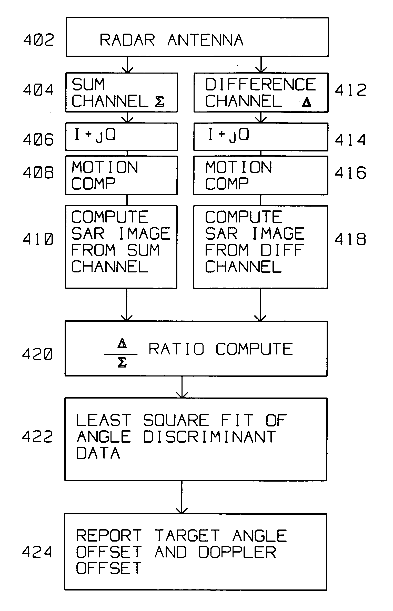
[0029] The present invention describes a robust detection technique for detecting fixed and moving ground targets using a common waveform in conjunction with the Sum Σ and Difference Δ antenna channels.

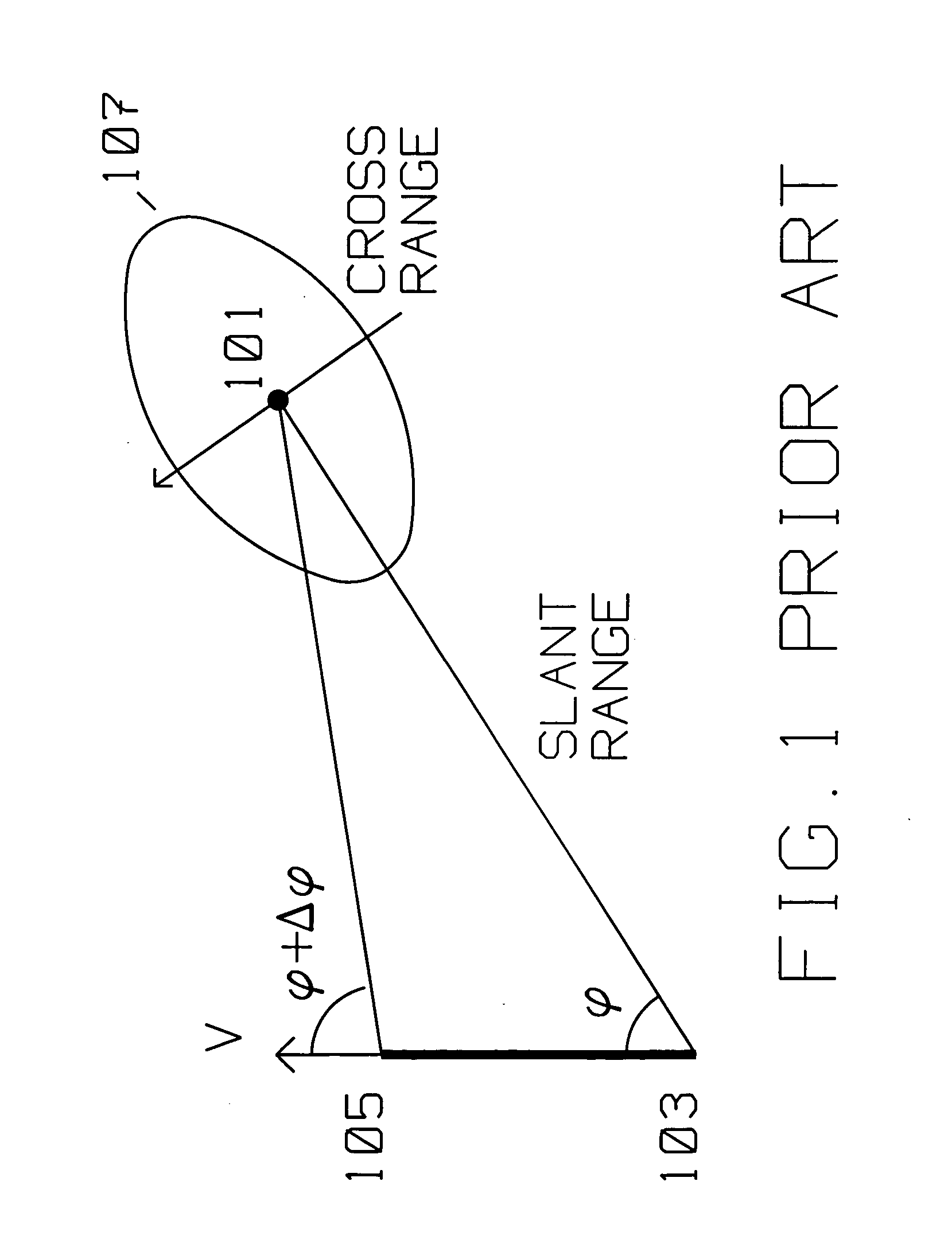
[0030]FIG. 1 shows the typical prior art geometric relationship between a moving platform carrying a radar transmitter / receiver using Synthetic Aperture (SAR) spotlight methods and target area 101 to be imaged by said radar transmitter / receiver. The moving platform is initially at position 103, travels with velocity V in the direction shown to position 105. In SAR spotlight mode, the SAR antenna is actively oriented towards scatterer 101 as the platform moves with respect to scatterer 101 with velocity V. The moving platform moves from position 103 to position 105, while adjusting the side looking angle from φ to φ+Δφ for spotlight mode so that the antenna keeps illuminating target area 101. Antenna illumination with radar energy covers area 107 during array times (frame length), and...


PUM


Abstract

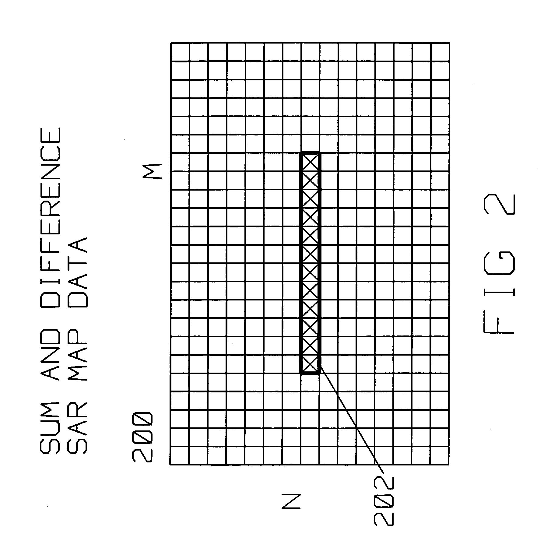
Detection of moving targets in SAR images is improved by a radar on a moving platform for generating a focused synthetic aperture image of a scene The scene contains a target described by pixels within the SAR image. The radar has a monopulse antenna having a sum channel output and a difference channel output feeding analog to digital converters for converting the sum channel output and difference channel output into respective digital streams concurrently. The digital streams generate a difference channel SAR image and a sum channel SAR image. Target ratios are computed for those pixels descriptive of a target within the scene. Background ratios are computed for pixels around the target. Target ratios and background ratios define respective least square fit of angle discriminants. Comparing the target least square fit of angle discriminant with the background least square fit angle discriminant identifies an angle offset and a Doppler offset of the target with respect to the background. The background least square fit of angle discriminant using background ratios is computed for a region around the target. A 20 by 20 sum synthetic aperture pixels is evaluated as a background around the target.

Description

BACKGROUND OF THE INVENTION [0001] 1. Field of the Invention [0002] This invention is in the field of fixed and moving target detection in Synthetic Aperture Radar (SAR) imaging. [0003] 2. Description of the Related Art [0004] Synthetic Aperture Radar (SAR) radar is used for ground mapping as well as moving / stationary target identification. The general principle behind SAR is to coherently combine the amplitude and phase information of radar returns from a plurality of sequentially transmitted pulses. These pulses are from a relatively small antenna on a moving platform. As the platform moves, the information contained in the pulses is combined to arrive at a high resolution SAR image. [0005] The plurality of returns creating a SAR image generated by the transmitted pulses along a presumed known path of the platform make up a frame length. Theoretically, during the frame length, amplitude as well as phase information returned from each of the pulses, for each of many range bins, is ...

Claims


Application Information

Patent Timeline
IPC IPC(8): G01S13/90
CPCG01S13/9023G01S13/9029G01S13/9092
Inventor KRIKORIAN, KAPRIEL V.ROSEN, ROBERT A.
Owner RAYTHEON CO
Learn More