Device for reading a barcode

a barcode and device technology, applied in the field of devices and methods for reading barcodes, can solve the problems of difficult use as hand scanners, inability to easily grasp one hand without additional measures, etc., and achieve the effect of reducing the quality of the polygonal mirror and reducing the air resistance of the mirror

Inactive Publication Date: 2006-07-13
DATALOGIC
View PDF43 Cites 13 Cited by
  • Summary
  • Abstract
  • Description
  • Claims
  • Application Information

AI Technical Summary

Benefits of technology

[0015] By providing the housing with a flat underside it can be placed in simple manner during use as a fixed scanner at a random position on a counter by an operator without a holder or the like being required. The housing moreover has such small dimensions in the longitudinal direction that it can be grasped easily with one hand to simplify use of the scanner as hand scanner.
[0045] According to a further preferred embodiment of the invention the rotatable polygonal mirror is arranged in the vicinity of a first corner of the housing and the fixedly disposed flat mirrors and / or the foldable mirror are arranged in the vicinity of an opposite corner of the housing. Such an asymmetrical arrangement of the polygonal mirror on the one side and the fixed mirrors and / or the foldable mirror on the other results in a space-saving inside the housing of the device such that it can take an even narrower form.

Problems solved by technology

When functioning as fixed scanners, however, these scanners must be placed in separate holders, which entails drawbacks in respect of utility and ease of operation.
These known scanners moreover have such large dimensions that they cannot easily be grasped in one hand without additional measures, which makes them difficult to use as hand scanner.

Method used


Image

  • Device for reading a barcode
  • Device for reading a barcode
  • Device for reading a barcode

Examples


Embodiment Construction

)

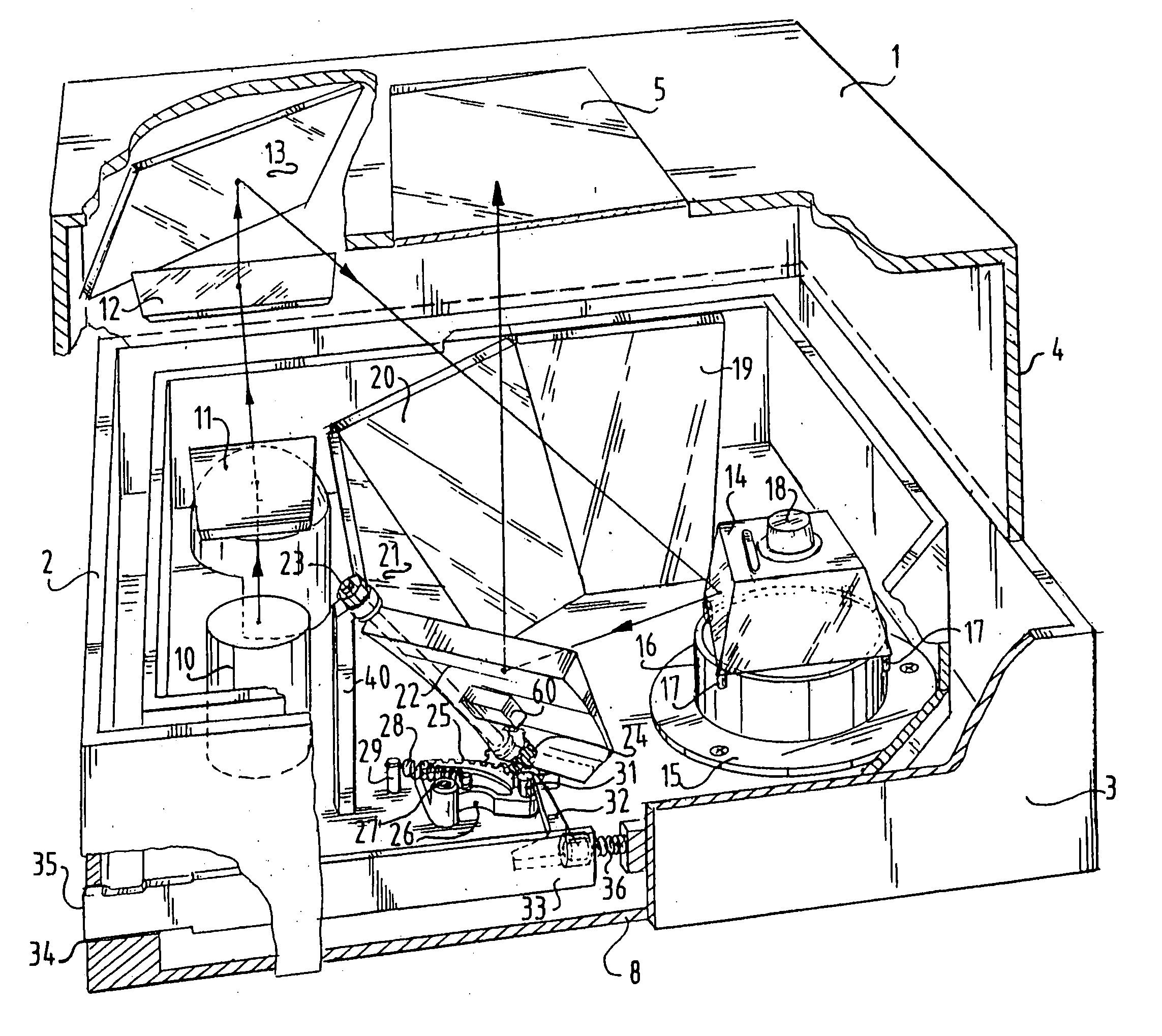
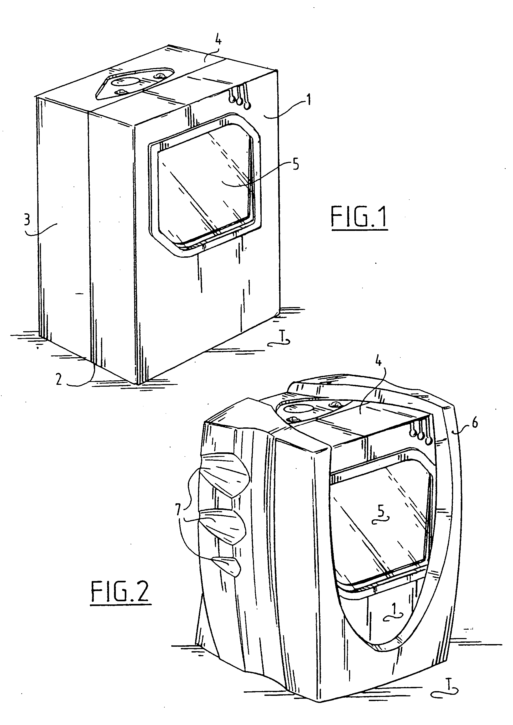
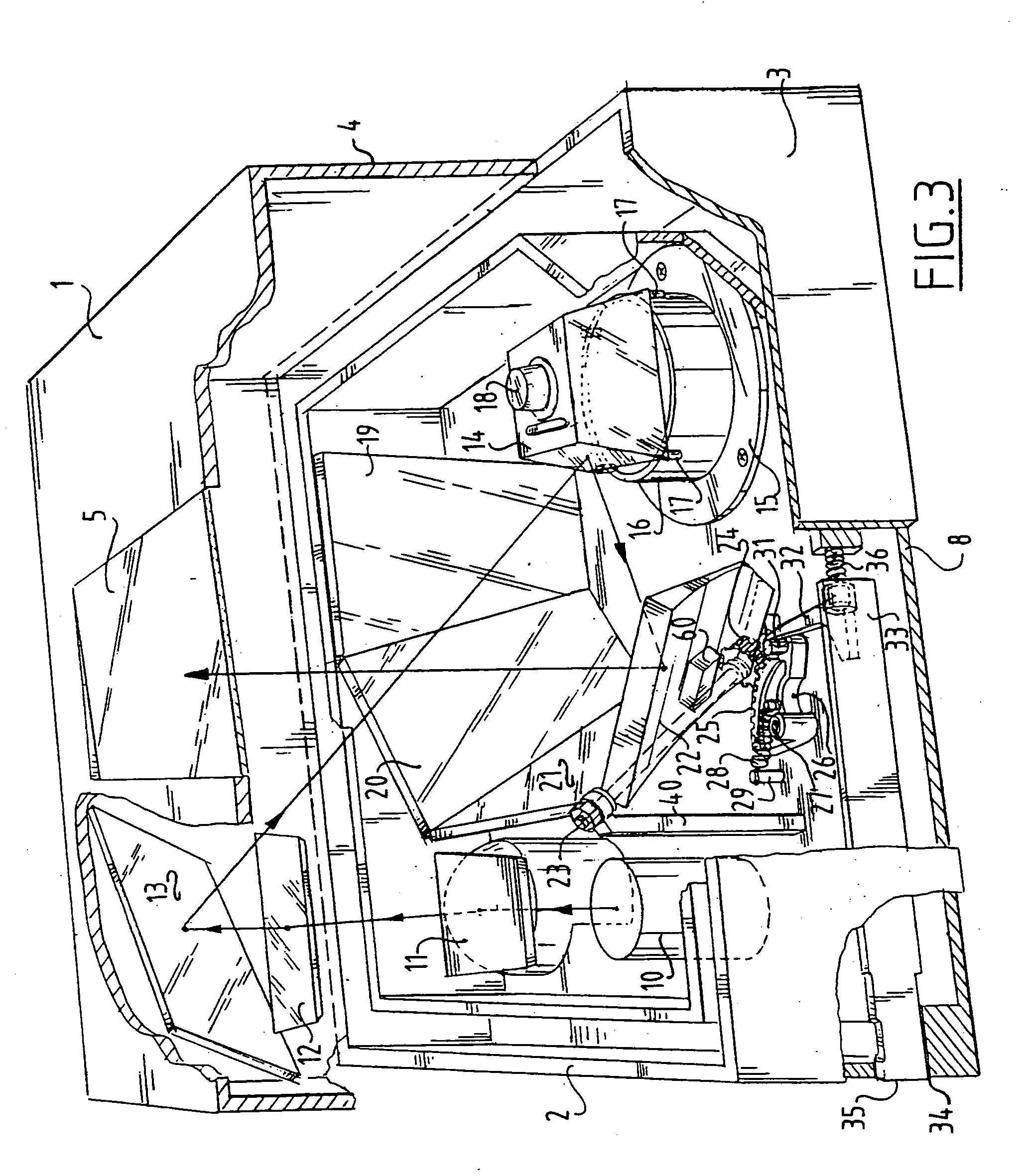
[0055] The scanner of FIGS. 1-6 comprises a housing provided with a flat bottom 2, a standing front wall 1, a standing rear wall 8, two standing side walls 3 and a top wall 4. Arranged in front wall 1 is a window 5 through which laser light exits and enters. In FIG. 1 the scanner is set down with its flat bottom 2 on a counter or table T of a shop and in this position the scanner functions as so-called fixed scanner, wherein the barcodes of the articles for recognizing are moved past window 5 by an operator (not shown). A beam of laser light herein exits through window 5. The laser light scattered by a barcode on an article subsequently re-enters the scanner via window 5 and is received there by a receiver 49 via a collector lens 50 and then processed, wherein the read barcode is decoded.

[0056] The scanner according to FIG. 1 is shown in FIG. 2, wherein however it is provided on the outside of the housing 1, 2, 3, 4, 8 with a protective or resilient holder 6, preferably manufactur...


PUM


Abstract

A device for scanning and / or recognizing one or more barcodes includes a laser light source for transmitting laser light; a rotatable polygonal mirror for reflecting the transmitted laser light; a number of fixedly disposed flat mirrors for reflecting laser light; a pick-up element for picking up laser light scattered by a barcode; a compact housing in which the laser light source, the polygonal mirror, the flat mirrors and the pick-up element are arranged, which compact housing is constructed from a substantially flat bottom side, a top side and standing walls arranged therebetween and wherein the distance between the standing walls ranges between 1.2-5.5 inches (3-14 cm).

Description

CROSS REFERENCE TO RELATED APPLICATION [0001] This application is a division of U.S. patent application Ser. No. 09 / 787,093, filed Jun. 12, 2001, which is the United States national phase of International Application No. PCT / NL99 / 00565, filed Sep. 10, 1999, which designated, inter alia, the United States, and which claimed the priority benefit of Netherlands Patent Application No. 1010088, filed Sep. 14, 1998.BACKGROUND OF THE INVENTION [0002] 1. Field of the Invention [0003] The present invention relates to a device and method for reading barcodes on objects, such as for instance articles in a shop. [0004] 2. Description of the Related Art [0005] Such devices or scanners can be divided into two types. The first type is a so-called fixed scanner which is disposed at a fixed location, for instance in or on a counter of a shop, wherein the objects for scanning are moved by hand along the front of the scanner by an individual. These fixed scanners are used particularly for small object...

Claims


Application Information

Patent Timeline
Patent Type & Authority Applications(United States)
IPC IPC(8): G06K7/10
CPCG06K7/10702
Inventor SCHONENBERG, CORNELIS REINIER JOHANNESNUNNINK, LAURENTIUS WILHELMUS
Owner DATALOGIC
Why Eureka
Try Eureka